Drawings & field notes
See how the
pieces relate.
Original evidence, drawn clearly. Enlarge a drawing to inspect it, or download the vector file for a sharp print.
 Enlarge drawing ↗
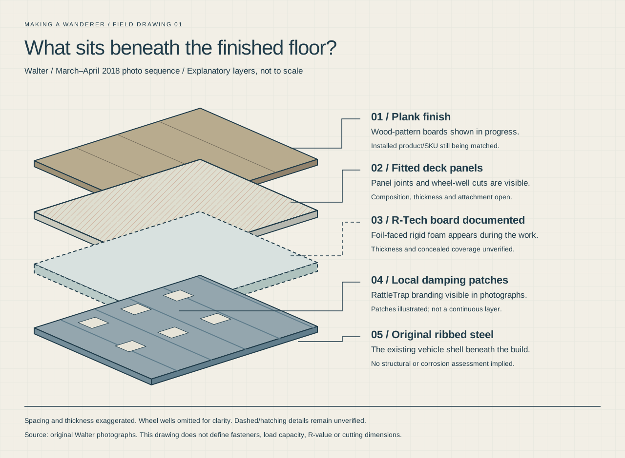
Photo-based assembly study
The floor, layer by layer
An exploded view of the documented floor stages, with unknown materials and thicknesses kept visible.
Download sharp vector drawing ↓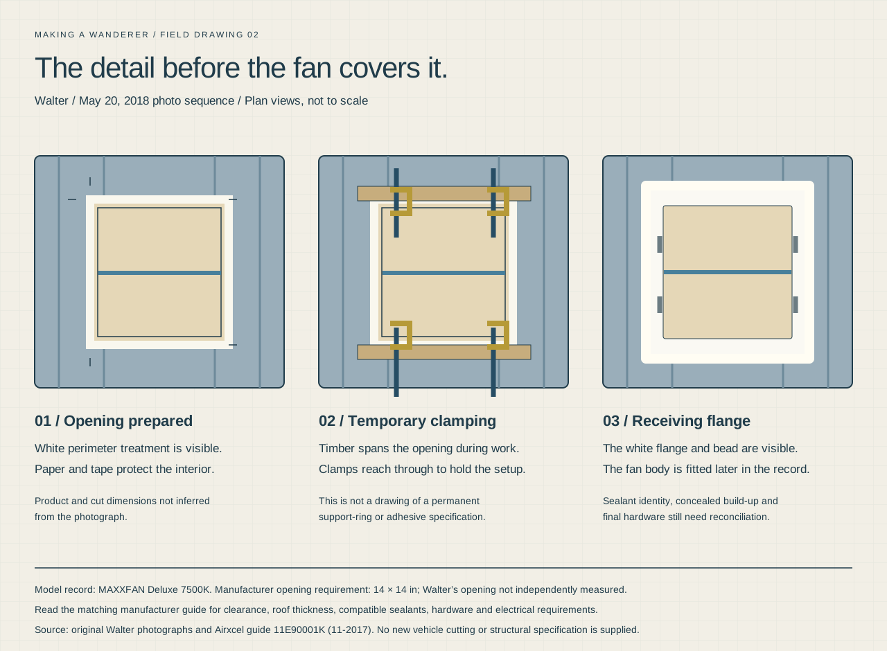 Enlarge drawing ↗
Photo-based detail drawing
Before the fan covers it
Three photographed stages explain the roof opening, temporary clamping and receiving flange.
Download sharp vector drawing ↓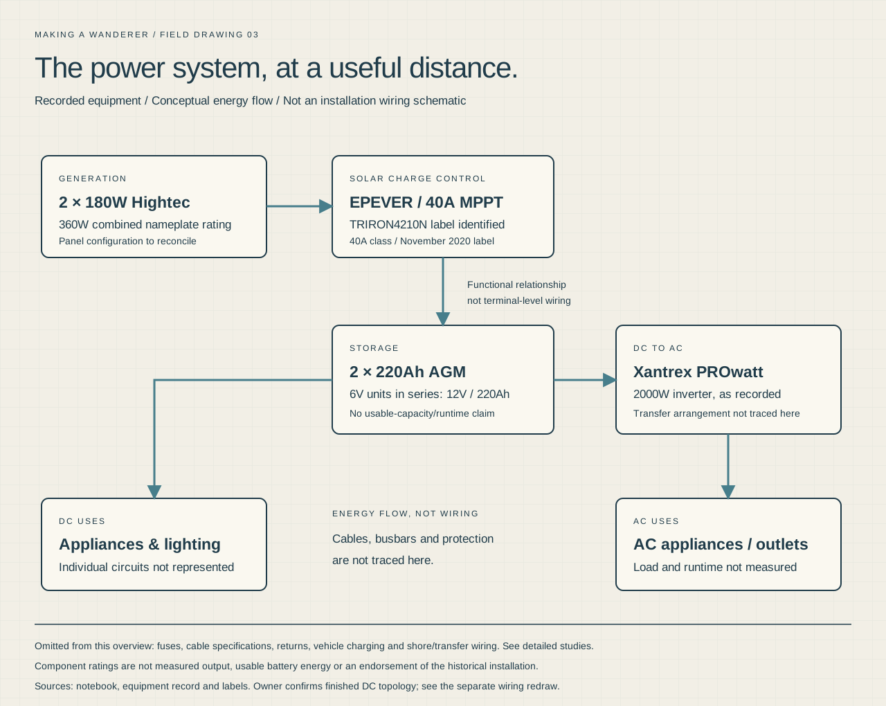 Enlarge drawing ↗
Component overview · not a wiring schematic
The recorded power system
A component overview with identified controller and series-connected 12V, 220Ah bank. See the separate DC wiring redraw for connections.
Download sharp vector drawing ↓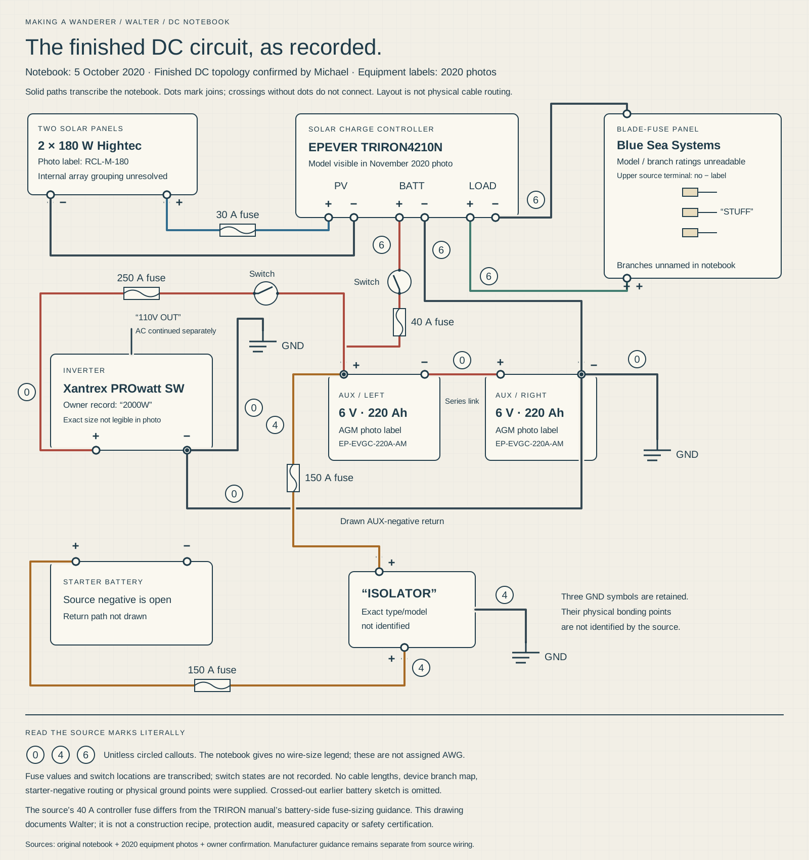 Enlarge drawing ↗
Notebook wiring redraw · source values
Walter’s finished DC wiring
A source-faithful redraw of the owner-confirmed October 2020 notebook. Handwritten fuse values and unitless cable callouts are preserved; suitability, cable units and individual load circuits require verification.
Download sharp vector drawing ↓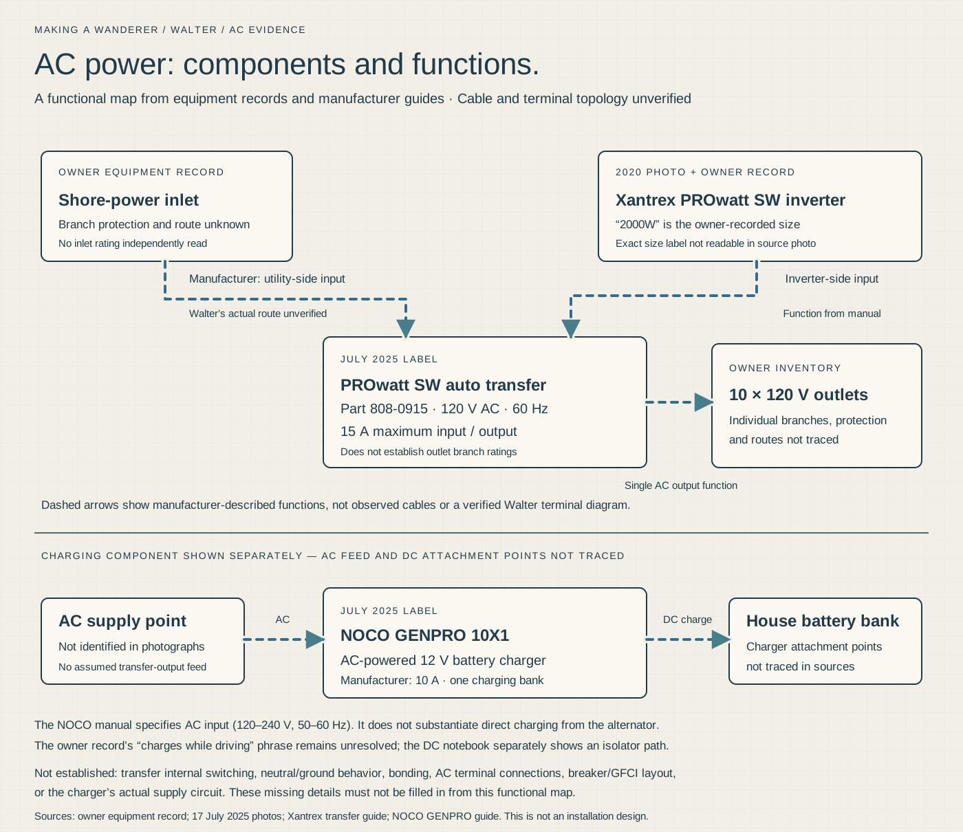 Enlarge drawing ↗
AC functional study · trace still needed
Shore, inverter and AC charging
Identified AC components and their functions, with concealed terminal routing and grounding left unresolved. This is a functional study, pending an installed-wire trace.
Download sharp vector drawing ↓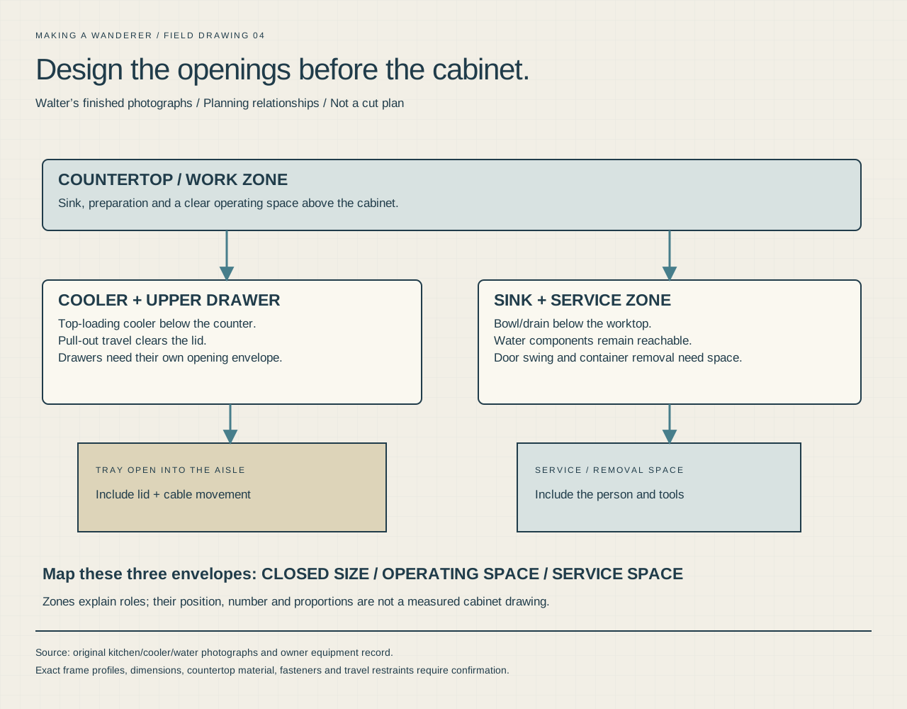 Enlarge drawing ↗
Planning relationship study
The kitchen’s three envelopes
Map closed equipment, operating movement and service access before sizing the cabinet.
Download sharp vector drawing ↓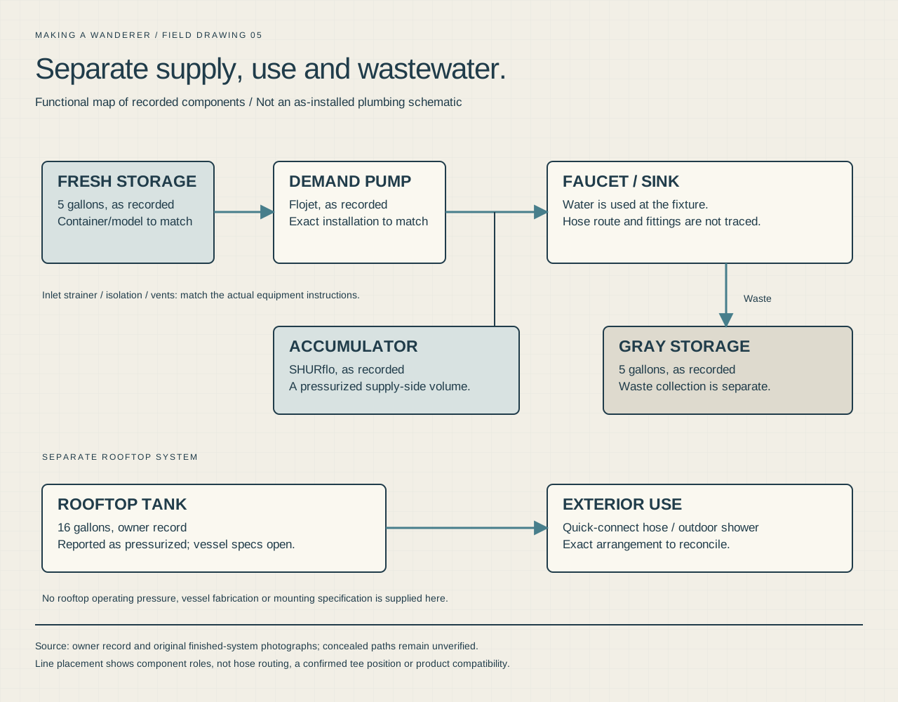 Enlarge drawing ↗
Functional system map
Supply, use and wastewater
A functional map of the recorded sink and separate rooftop systems. Concealed hose routes and pressure settings remain unverified.
Download sharp vector drawing ↓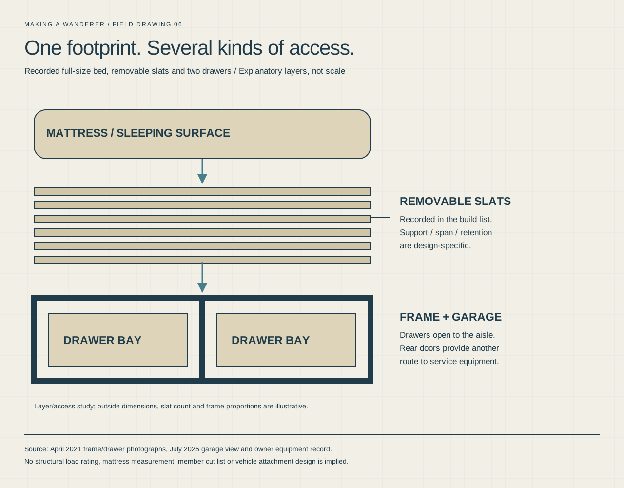 Enlarge drawing ↗
Photo-based access study
The bed and the space below
An explanatory layer/access study of the recorded mattress, removable slats, frame and drawer bays.
Download sharp vector drawing ↓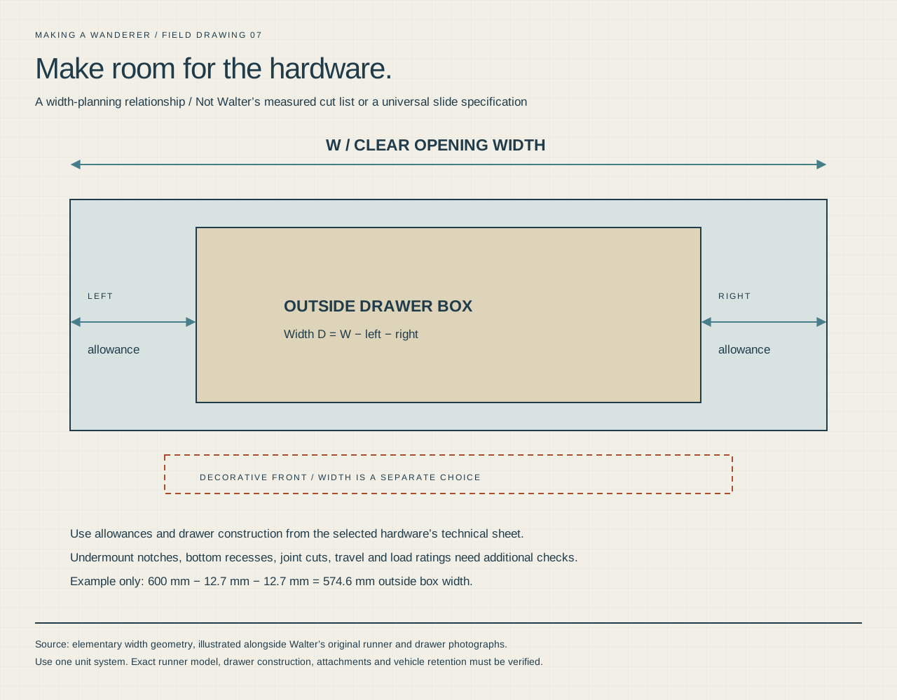 Enlarge drawing ↗
Geometry worksheet
Make room for the hardware
The relationship between opening width, side allowances and outside drawer width, with the front treated separately.
Download sharp vector drawing ↓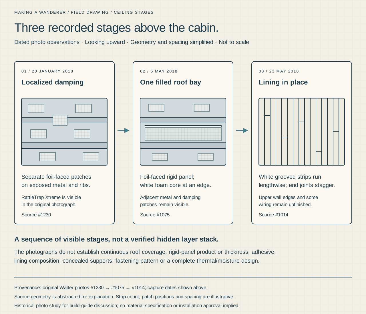 Enlarge drawing ↗
Dated photo-stage comparison
Three views of the ceiling build
Dated views separate localized damping, a foil-faced rigid panel and grooved lining. This is a comparison of visible stages, not a verified final cross-section.
Download sharp vector drawing ↓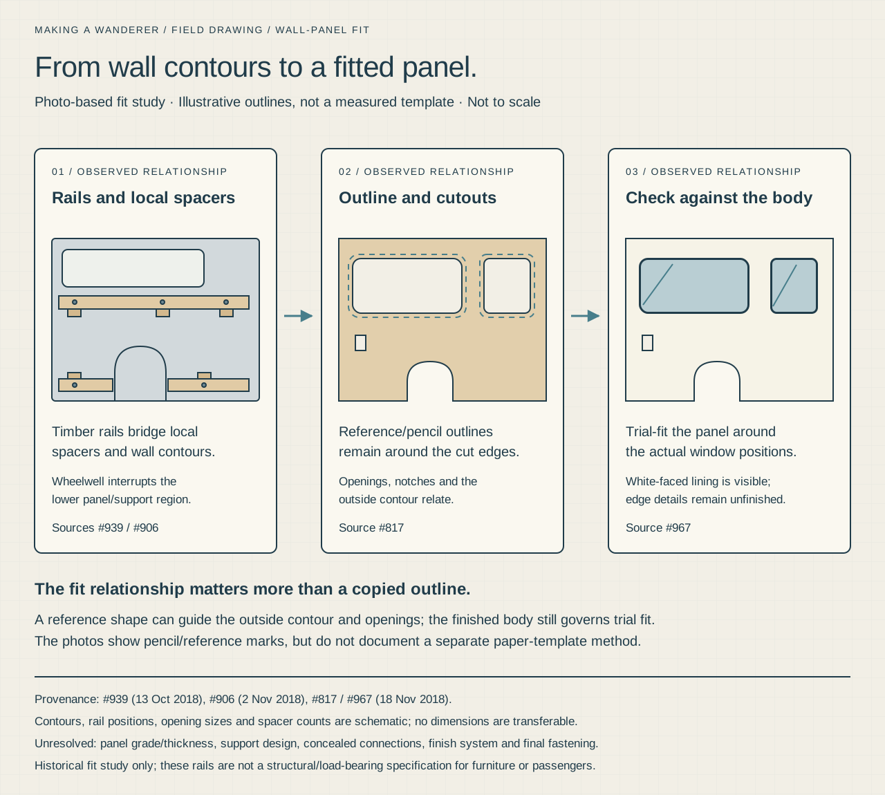 Enlarge drawing ↗
Photo-based fitting study
From wall supports to a fitted panel
Rails, spacers and opening relationships explain the photographed wall fitting. Dimensions and concealed attachments remain unresolved.
Download sharp vector drawing ↓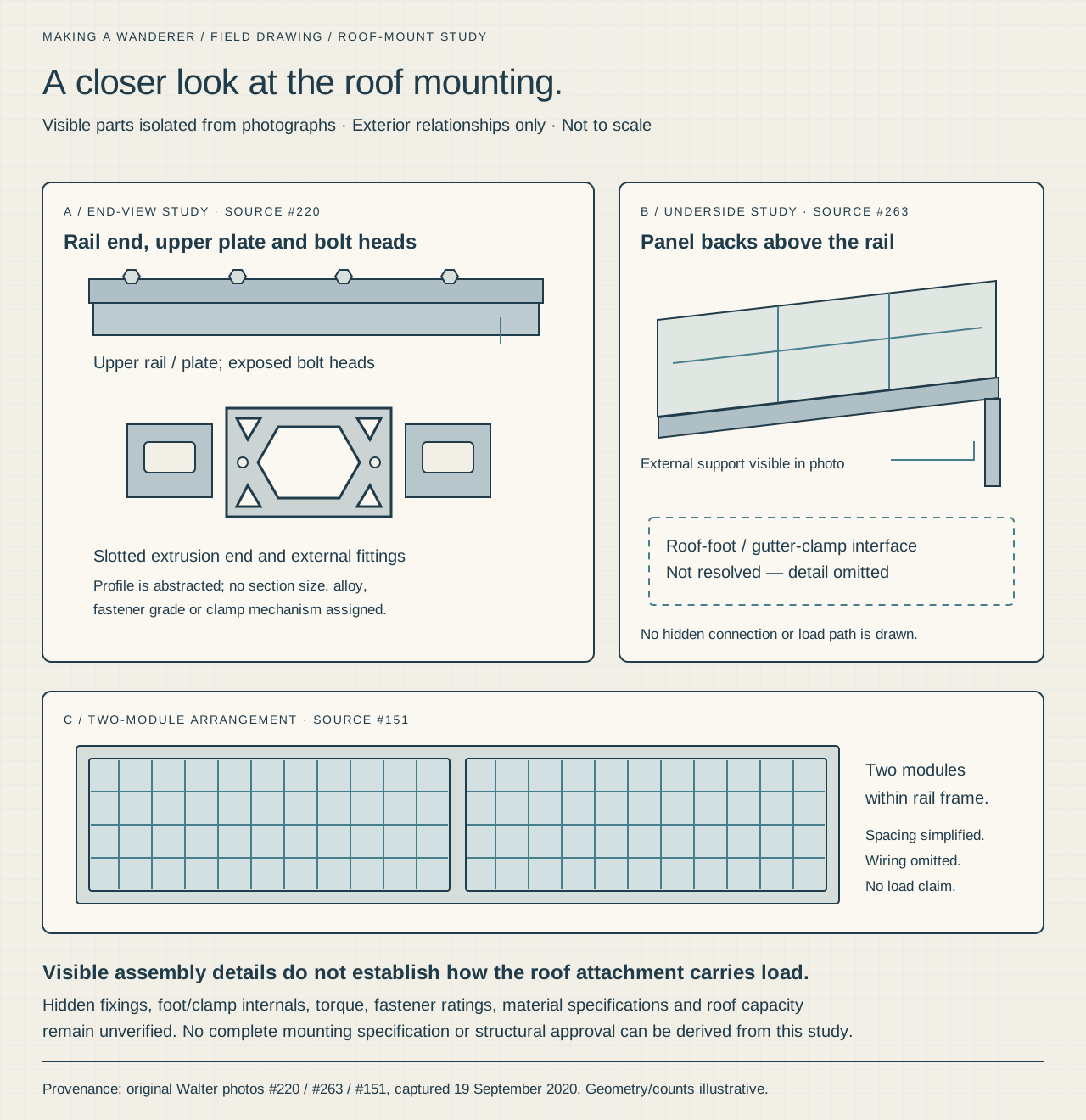 Enlarge drawing ↗
Visible-interface study · incomplete mounting design
The visible roof-mount interfaces
Extrusions, plates, bolt heads and panel backs are shown from photographed views. The unresolved roof foot and structural load path are deliberately omitted.
Download sharp vector drawing ↓A drawing’s job is to explain
These illustrations identify their source and verification limits. None is a measured cut plan, load assessment or approved electrical installation design. The original handwritten electrical page remains available in the electrical notebook.