Read the ceiling as a set of documented stages
The finished ceiling sets much of Walter’s atmosphere, but the early photographs explain the work above that surface. In January 2018, localized foil-faced damping patches sit on the exposed roof. A May photograph shows a rigid foil-faced panel fitted between ribs. Later that month, white grooved lining runs lengthwise through the interior.
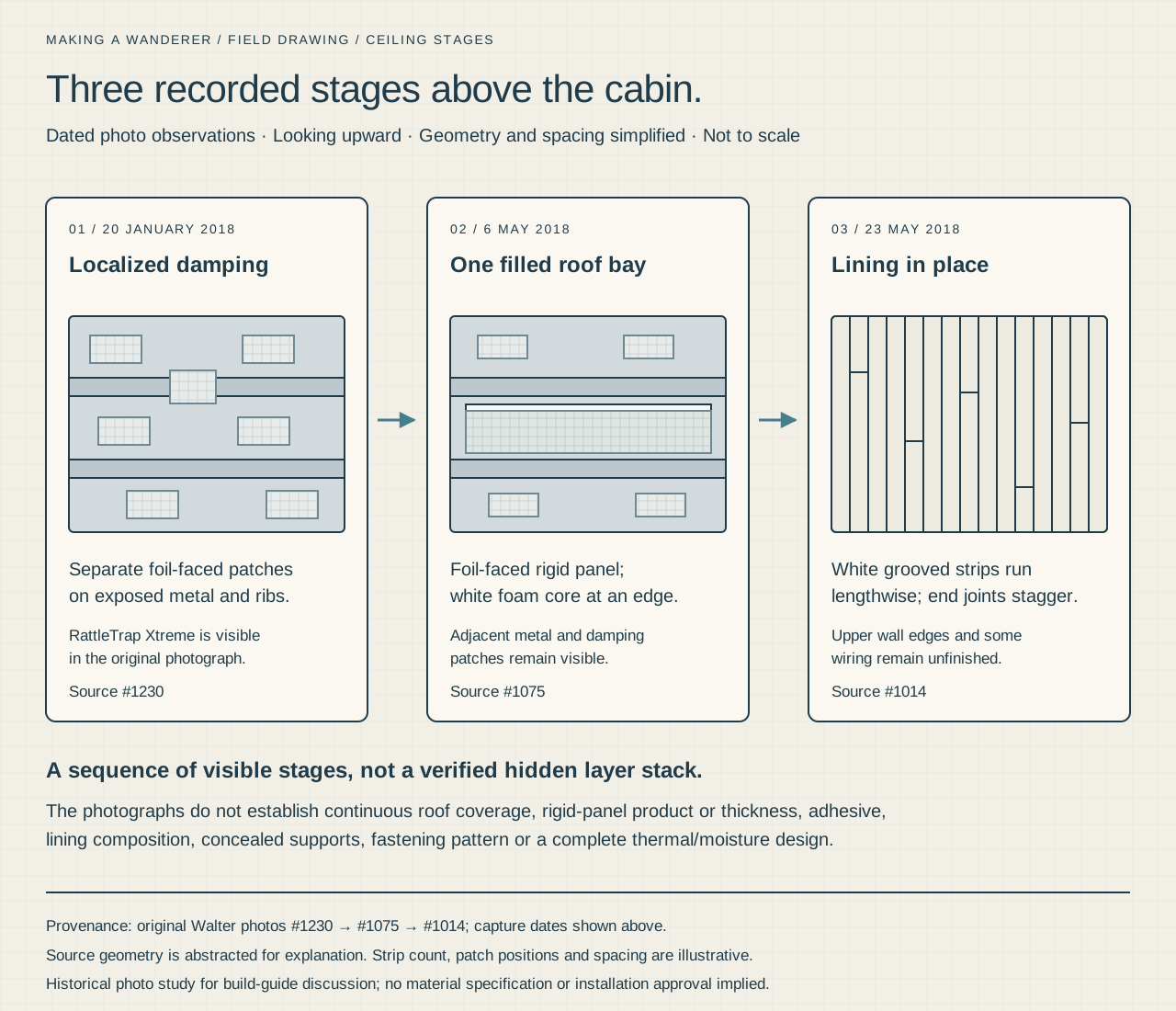
The drawing keeps those observations in separate stages. It does not fill the gaps with an invented support grid, insulation product or fastener schedule. For another conversion, those interfaces need to be designed for its actual roof and materials.
 Enlarge drawing ↗
Dated photo-stage comparison
Three views of the ceiling build
Dated views separate localized damping, a foil-faced rigid panel and grooved lining. This is a comparison of visible stages, not a verified final cross-section.
Download sharp vector drawing ↓Photographed stage
1 / Keep damping and lining jobs distinct
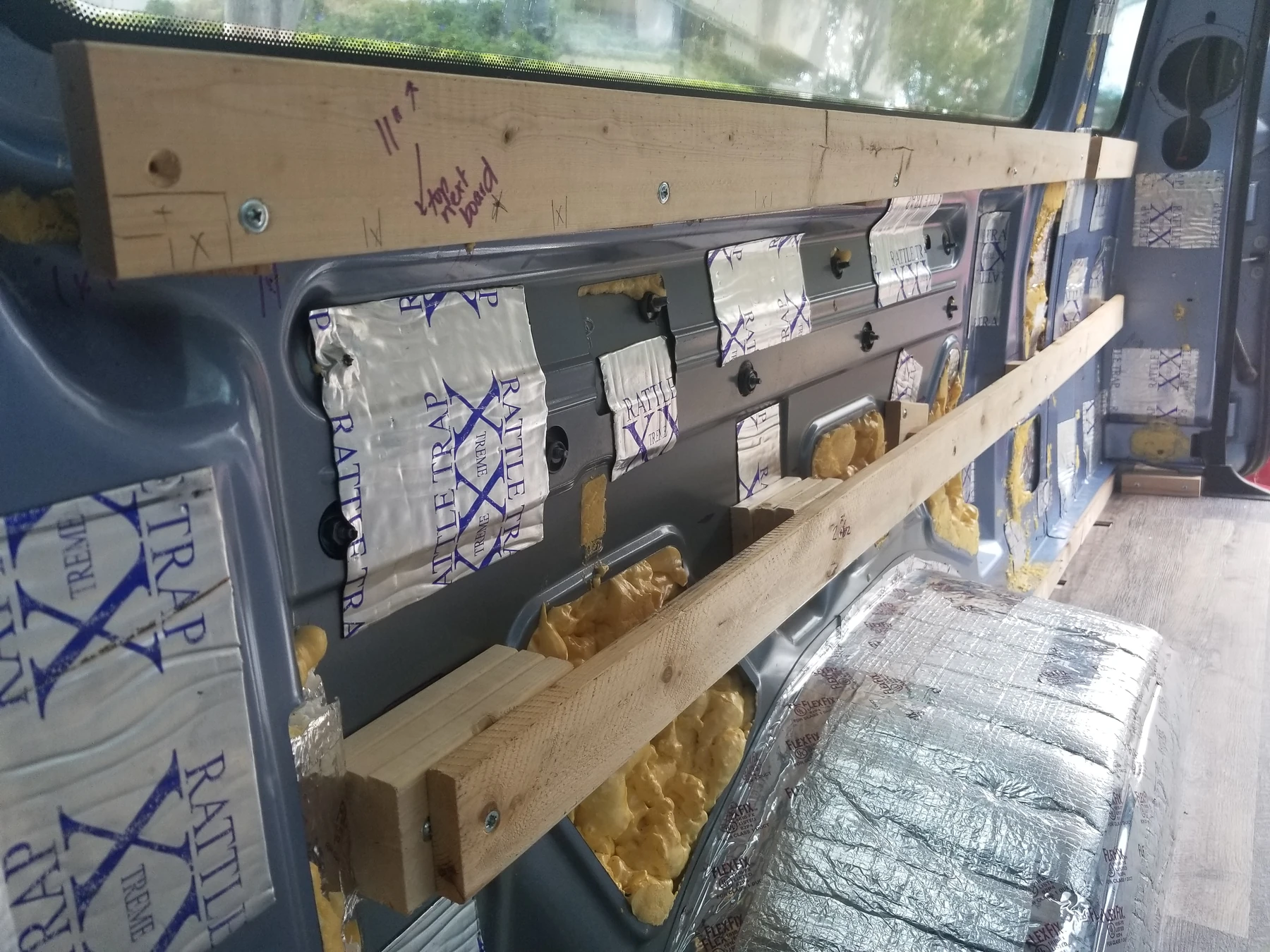
The January photograph shows individual branded patches on roof panels, with steel visible between them. The ribs and openings remain easy to inspect.
Describe each material by its job when planning a roof build-up: damping, thermal control, support, wiring space and finish are separate questions. A shiny surface does not establish an insulation value, moisture strategy or the suitability of a different product.
Photograph placement and the surrounding shell before the next layer covers it. Keep the actual product instructions and installation conditions with the build record.
Photographed stage
2 / Fit the panel to the real roof geometry
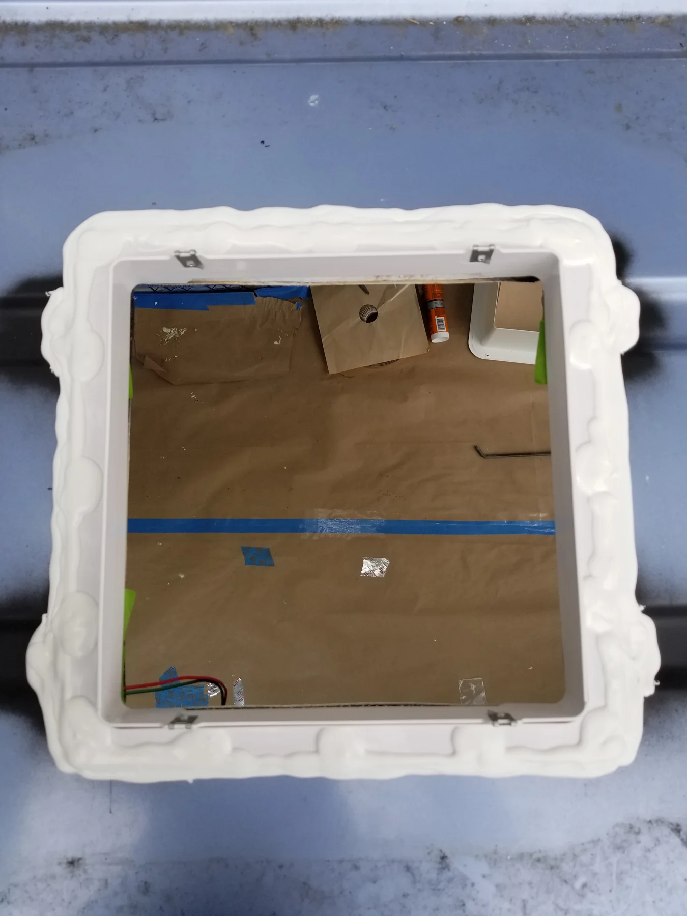
The May 6 image shows a pale, foil-faced rigid panel between roof members. The neighboring ribs and damping patches are still visible, making its relationship to the shell clear.
For a similar task, work from a template and check edges, obstructions and the intended support arrangement before preparing final pieces. Keep access around roof ventilation and planned service routes. The photograph does not establish the panel’s chemistry, thickness, thermal performance or hidden retention.
Walter’s fan-opening sequence belongs to the same broader roof work. Coordinate the opening, trim depth and service access with the ceiling instead of designing each in isolation.
Photographed stage
3 / Establish the finish lines and service openings
By May 23, narrow white grooved strips run along the roof, with end joints visible at different positions. Unfinished upper-wall edges and wiring remain exposed. This view records the appearance and order of work without revealing every fixing behind it.
Lay out the finish from repeatable references. Check how narrow edges will end at walls, the fan trim and door areas, and how removable pieces will be identified. Plan the access needed to inspect roof equipment and service wiring.
The selected record does not identify the exact lining material or fastening pattern. A finished appearance cannot establish its attachment strength or the suitability of those details for a different material.
Planning step
4 / Develop lighting with the ceiling, not after it
The 2025 interior photographs show narrow ceiling boards and warm perimeter lighting. The lights emphasize the room’s length and leave the main surface visually calm.
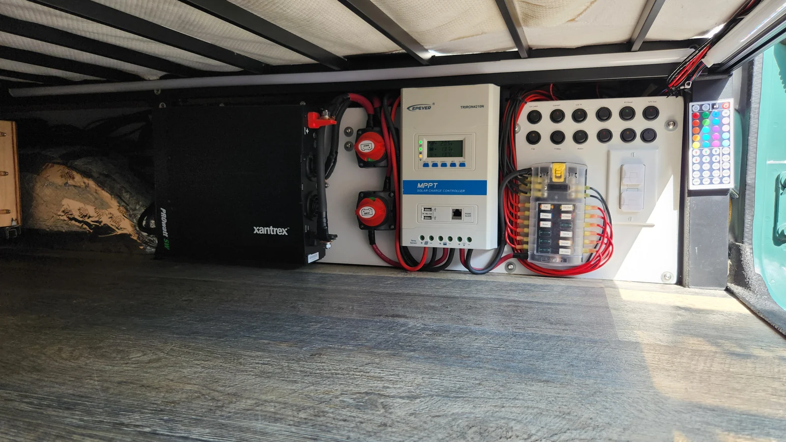
For another van, decide where light is needed for cooking, reading, storage and movement before closing service routes. Keep electrical connections accessible and use the actual equipment instructions for mounting and separation requirements. The finished photograph does not show a wiring method or authorize burying connections behind a permanent surface.
The later photograph is evidence of the finished look. It does not prove that every 2018 piece remained unchanged through the rest of the conversion.
Keep a record of what the lining hides
- Identify each material and retain its actual instructions.
- Record roof contours, openings, supports and service routes.
- Check fan trim and other equipment against the finished build-up.
- Document concealed attachments and wiring before closing them.
- Demonstrate removal of the intended service panels.
- Inspect the completed roof equipment and finish using the applicable installation checks.
The wall guide continues the same idea around windows, wheelwells and the edges of the room.
About these notes
Dated originals show localized roof damping, a foil-faced rigid panel and white grooved lining. A later photograph shows the finished slatted ceiling and lights. Exact panel chemistry, thickness, supports, fastening, wiring and whether the later finish retains every earlier piece are unresolved.