The important work is at the edges
A van wall is full of interruptions: curved steel, windows, wheelwells, trim and service routes. A flat sheet only becomes useful after its edges and supports have been worked out.
Walter’s October and November 2018 photographs preserve those interfaces before the finish makes them look simple. Horizontal timber rails sit over local spacers. The lower wall changes shape around a wheelwell. A prepared panel contains large openings, small cutouts and edge notches.
Use the sequence to understand how a wall is developed, then measure and specify the materials for the actual vehicle. The drawing shows relationships without assigning Walter’s unresolved dimensions or attachments to another build.
 Enlarge drawing ↗
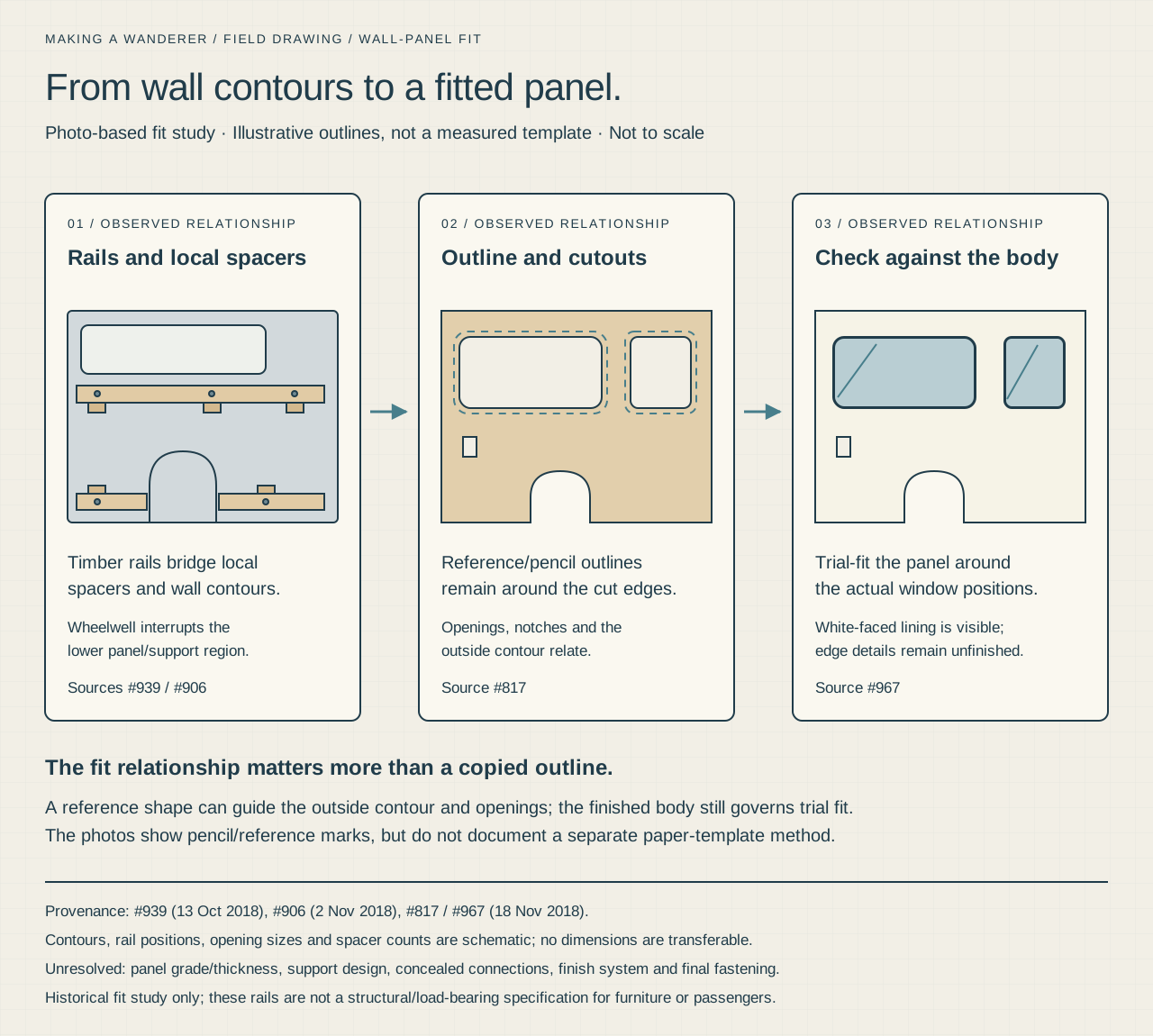
Photo-based fitting study
From wall supports to a fitted panel
Rails, spacers and opening relationships explain the photographed wall fitting. Dimensions and concealed attachments remain unresolved.
Download sharp vector drawing ↓Photographed stage
1 / Establish the support and service plan
The October 13 photograph shows broad timber strips crossing the wall, with local spacer blocks and visible fastener heads. Damping patches and cavity fill remain visible between them. Handwritten marks record part of the work, but their measurement meaning has not been reconciled.
For another van, identify what each member will support and where the lining can be removed. Coordinate service routes, window trim and furniture interfaces before settling its position. A wall-lining support is not automatically a suitable attachment for heavy furniture.
Keep a record of the chosen member, fasteners and vehicle interface. The photographs show placement; they do not establish hidden fixings, fastener grade, structural capacity or a universal rail spacing.
Photographed stage
2 / Follow the shape through the lower wall
The November 2 detail shows the rails around the wheelwell. Local spacers and an angled piece handle changes in the shell, while reflective covering follows the wheelwell surface. The plank floor is already in place.
Check this area at the heights where drawers, bed frames and cabinet sides will meet it. Include finished floor thickness, trim and access to existing vehicle features. A convenient straight line on a drawing can conceal an awkward obstruction inside the actual bay.
The visible reflective covering is recorded by appearance. Its product, complete build-up and thermal performance are not established here.
Photographed stage
3 / Transfer openings from a stable reference
A November 18 photograph shows a light wood-grain panel with a large rounded opening, a smaller opening and edge notches. Pencil lines remain at some cut edges. The photo establishes the visible panel shape, without proving its internal construction or thickness.
Use a template that can be located repeatably against the intended mounting references. Mark which side faces the room and which edges are final. Check the actual trim and equipment around an opening before transferring it to a finished panel.
Keep the first fitting reversible. Identify where the panel touches the shell and where a gap is intentional. Material movement, edge clearances and fastening requirements belong to the selected product and support design.
Photographed stage
4 / Trial-fit the whole panel
The later selected image shows a white-faced panel around the side windows. The wheelwell and upper edge remain unfinished, and a small rectangular opening is visible below the window.
Check the complete piece in place: openings, door edges, neighboring panels, floor junctions and access points. Fit the real trim where possible. A panel can match its template and still conflict with a handle, curtain fitting or another finished part.
The finished fastening and surface composition are not visible in this view. Temporary holding arrangements elsewhere in the archive do not establish a permanent attachment method.
Planning step
5 / Keep the wall useful after it looks finished
Document cable and hose routes before enclosing them. Identify panels intended for removal and retain a clear route to their fixings. Coordinate furniture so a drawer or bed frame does not block the only access to a service panel.
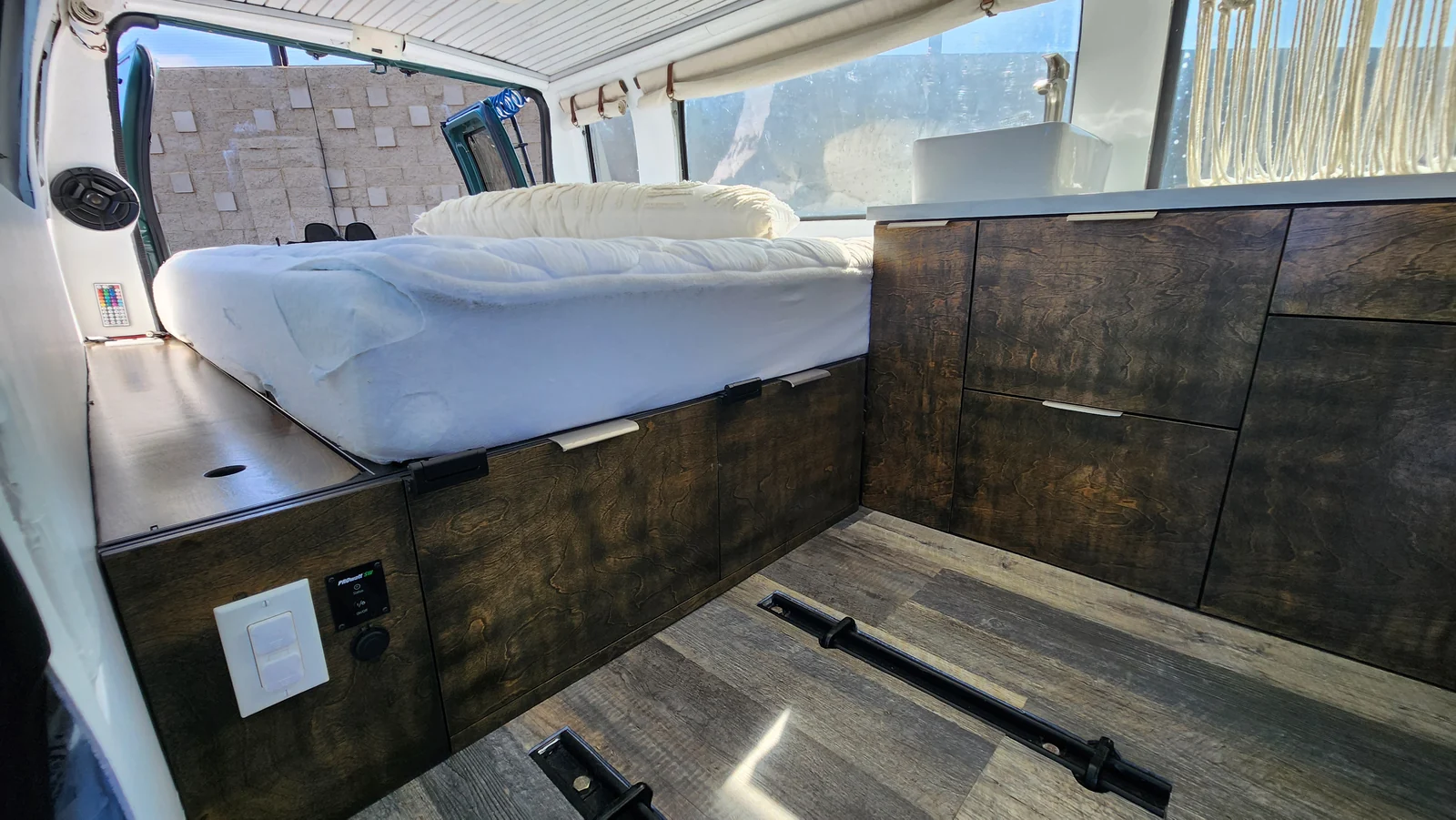
Walter’s kitchen and bed depend on the same wall contours. Bring their finished sizes into the wall mockup early, rather than treating lining as a cosmetic layer added after every other dimension is fixed.
The wall-fitting checklist
- Use references that remain visible and repeatable during fitting.
- Record actual panel material, thickness and product requirements.
- Check windows, trim, floor junctions and neighboring furniture together.
- Design furniture attachments separately from decorative lining.
- Photograph concealed routes and attachments before closing them.
- Demonstrate service-panel removal with the finished furniture in place.
The result should be a room that still gives access to the vehicle and systems it surrounds.
About these notes
Original photographs establish timber rails/local spacers, a covered wheelwell, cut wood-grain panel and trial white-faced lining. Exact panel construction/thickness, insulation chemistry, attachment schedule and structural capacity remain unresolved. Handwritten marks are not reproduced as dimensions.