Write the jobs the space has to do
A useful campervan plan begins with daily routines. Where does someone sleep? Where can a second person sit while the cooler is open? How does a wet water container leave the cabinet? Where can tools, bedding and dirty shoes go without moving everything else?
Walter answers those questions with a rear bed, side kitchen, front seating, aisle-facing drawers and rear service access. The details are specific to a 1996 E-350, but the planning method carries across vehicle shapes. Begin with the equipment and people your van needs to accommodate.
Write a short brief before drawing furniture: occupants, sleeping arrangement, cooking routine, water use, electrical loads, bulky belongings and places the van must fit. Add a separate list of optional comforts. This makes tradeoffs visible when two items want the same space.
Planning step
1 / Measure the shell in several places
Measure at the floor, worktop and bed heights. Van walls curve; the widest point on the floor does not establish the width at shoulder level. Record wheelwells, door openings, existing service routes and surfaces that will gain lining.
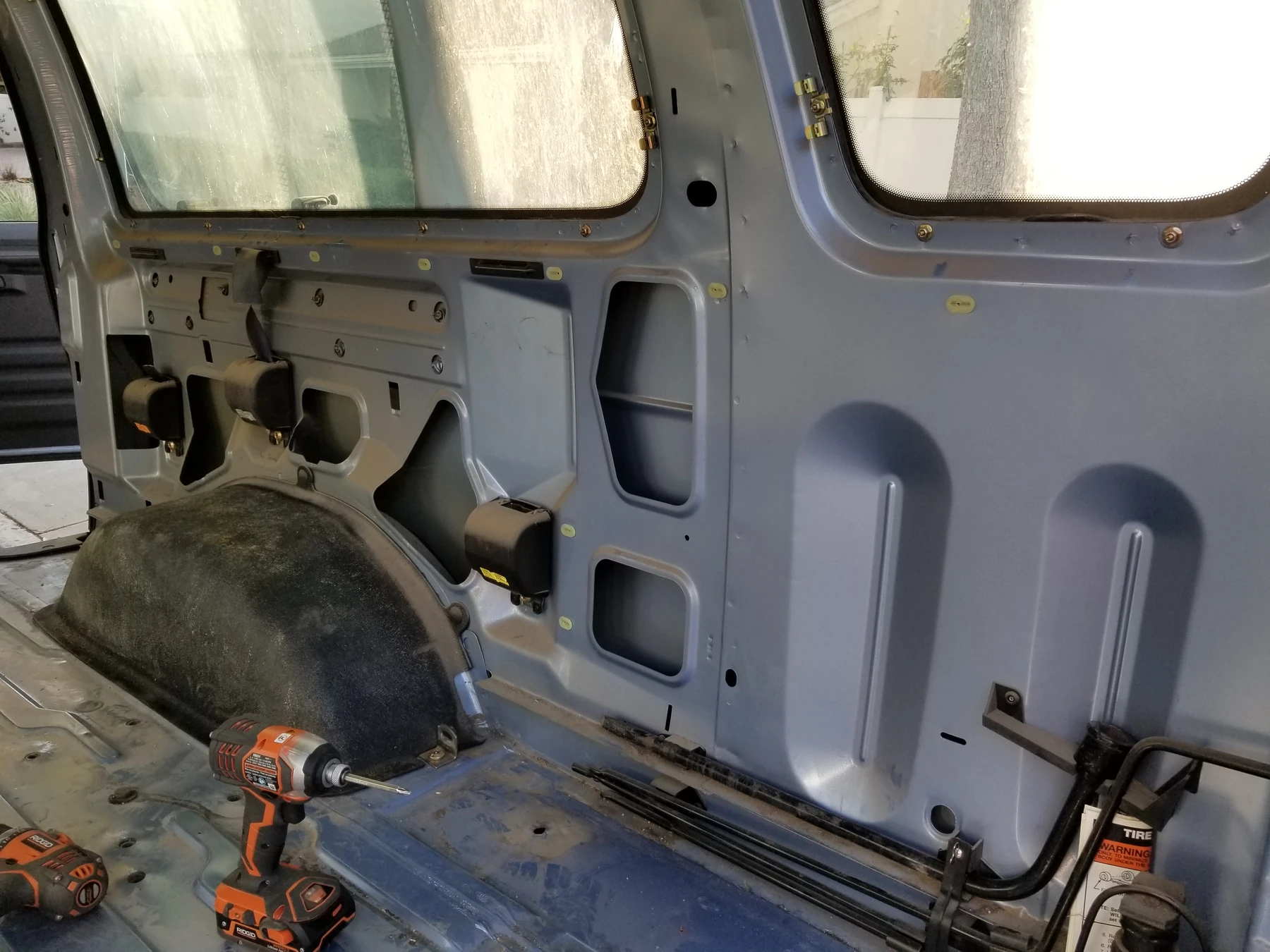
Walter’s January 2018 photograph shows measuring tools and loose panels in the stripped interior. It records an early study, rather than a finished dimensioned plan. The later floor and wall work changes the surfaces available to furniture.
| Check | Record before committing |
|---|---|
| Shell | Widths at useful heights; floor length; headroom; wheelwell positions; body contours. |
| Entry and escape | Door openings, step heights, occupied aisle, access to door handles and a clear exit route. |
| Finished surfaces | Allowances for floor, wall and ceiling build-up; window trim and handles. |
| Services | Equipment removal routes, cable/hose paths and inspection access. |
| Vehicle limits | Actual vehicle ratings, axle loads and the chosen equipment/attachment requirements. |
Planning step
2 / Put the plan on the actual floor
In July 2020, Michael marked the finished floor with blue tape. The labels identify the bed edge, kitchen edge, front of the back seat and bed-leg positions. That photograph makes the layout process tangible: the future furniture is being tested inside the real shell.
Use tape, cardboard and temporary boxes to check your own plan. Include finished panels, handles, mattress edges and the space a person occupies. Try standing at the counter, climbing into bed and moving from a seat to the door.
The labels are useful evidence of the work, but they do not provide a scale. Take measurements from the actual van and selected equipment, then update the drawing when the mockup changes.
Planning step
3 / Draw movement as carefully as furniture
A closed cabinet can look beautifully compact. Its cooler tray, drawers, doors and lids require additional space during use. Make a second set of outlines for those movements and check neighboring items together.
Walter’s extended cooler and under-bed drawers use the aisle at different times. Their value comes from bringing contents into reach. A layout should let someone use that reach without becoming trapped between an open box and a seat.
The kitchen guide separates closed, operating and service envelopes. Apply the same idea to the bed, seating and water storage. A removable component also needs a route through the finished interior.
Planning step
4 / Leave room for the things behind the finish
Plan access to electrical protection, battery connections, pump fittings, drawer hardware and vehicle service points before enclosing them. A bed platform can make a generous garage while still allowing its equipment to be reached from the rear.
Walter’s removable slats and frame, container access and electrical service area show how strongly these decisions overlap. Furniture dimensions and service routes should be developed together.
Record a removal demonstration for the largest service item. Identify the screws, clips or connections that must be reached, the tools needed and the clear path out. A hatch that reveals a component but cannot pass it is only part of the solution.
Planning step
5 / Turn the layout into a build sequence
Use the sequence to protect access. Survey and repair the shell before covering it; establish floor and lining allowances before final furniture dimensions; plan cable and hose routes while both sides remain visible. Fit and test assemblies before decorative fronts hide their adjustments.
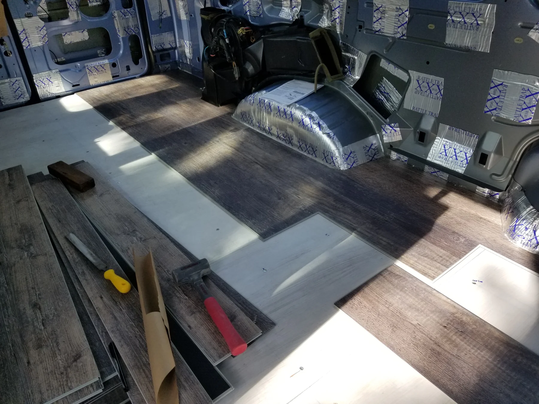
The photographs show Walter developing over several years. The floor appears in 2018, the body/paint record in 2019, roof and system details in 2020, and drawer boxes in 2021. Those dates document photographed stages; they do not establish uninterrupted construction time.
- Survey the vehicle and record the intended use.
- Inspect and prepare exposed surfaces; resolve vehicle-specific work.
- Mock up the finished layout and service clearances.
- Coordinate floor, roof ventilation, lining and service routes.
- Fit systems and furniture with inspection/removal access.
- Check the occupied space and loaded moving parts before final finishing.
Planning step
6 / Budget by systems and unresolved decisions
Separate the vehicle purchase from conversion materials, repairs, outside labor and ongoing ownership costs. Keep a list of quantities and exact products, then distinguish an old receipt from a current quotation.
Walter’s cost notebook demonstrates why: the effective van acquisition cost, bundled paint work and individual equipment purchases describe different scopes. They do not add up to a complete conversion total.
Price the interfaces as well as the headline equipment. Frame connectors, slides, cable terminations, fittings, protective finishes and access hardware can determine whether the major component works in the chosen location. Record uncertainty rather than filling every blank with a guessed number.
A layout is ready when the routines work
- Everyone can sit, move, sleep and leave the van in the intended configuration.
- Lids, drawers and doors complete their movements with neighboring equipment in place.
- Water containers and service equipment can actually be removed.
- Vehicle weight limits, loads and attachment designs have their own verified basis.
- The working drawing reflects the finished surfaces and latest mockup.
- Costs and unknowns are recorded by system, with sources attached.
Start with the guide for the system you are planning next. Keep returning to the full-size mockup as the details become real.
About these notes
Walter’s early measuring photograph, July 2020 floor labels and finished-build record show actual layout work. This guide provides a general planning sequence; no scale drawing, vehicle dimensions, mattress size, structural attachment or universal equipment specification is inferred.