The bed is also the roof of the garage
Walter’s bed occupies the rear living space, but its underside defines another useful room: the garage. Drawers open toward the sliding-door aisle, while the rear doors provide access below the sleeping platform.
This creates several design questions at once. The mattress needs enough room for comfortable use. The frame must support the intended loads. Drawers need travel and hardware space. Electrical and water equipment must remain reachable. The removable slats described in the build record add another route to the space below.
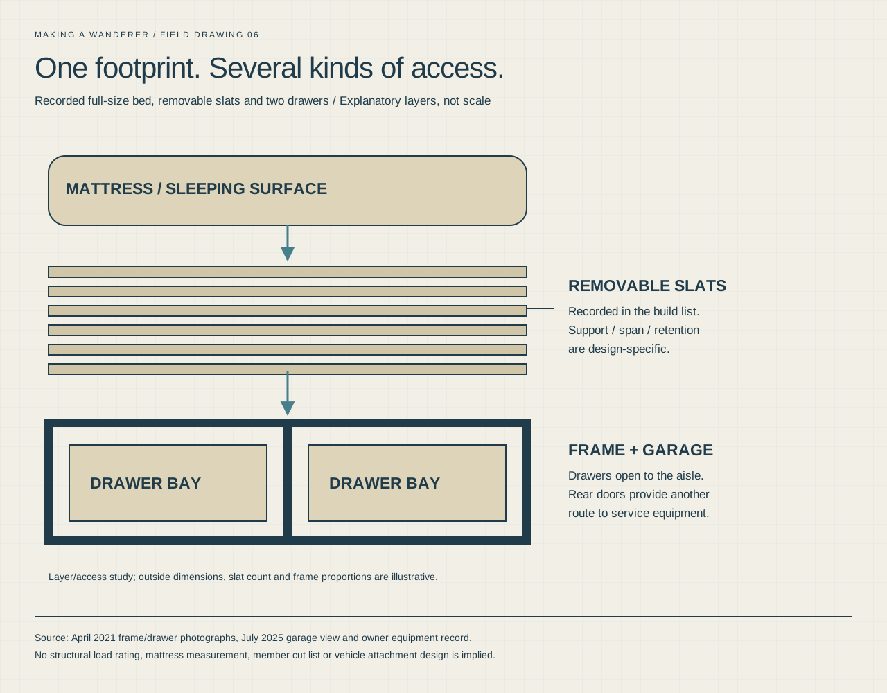
The drawing separates these layers and access directions. Its proportions explain relationships; they do not establish Walter’s measured frame dimensions or a structurally verified design for another van.
 Enlarge drawing ↗
Photo-based access study
The bed and the space below
An explanatory layer/access study of the recorded mattress, removable slats, frame and drawer bays.
Download sharp vector drawing ↓Planning step
1 / Set the sleeping position and garage height together
Start with the actual mattress and the way people will get into bed. Measure the finished wall surfaces where the mattress will sit, including the curve of the body at that height. Record the ceiling clearance with the mattress in place rather than measuring only to the bare frame.
Next, place the largest objects that must live underneath. Their height includes lids, handles, mounts and the room needed to remove them. Bed height is a trade-off between those storage needs and the space above the mattress.
| Decision | What to record |
|---|---|
| Sleeping surface | Actual mattress dimensions and thickness; entry route; head/foot clearance; nearby window and lighting controls. |
| Garage | Largest stored item; service equipment; access from rear doors; clearance below frame rails and slats. |
| Drawers | Opening direction; loaded box height; runner positions; full travel into the aisle. |
| Structure | Profile and joint specifications; support arrangement; loads; vehicle attachments; accessible inspection points. |
Photographed stage
2 / Read the frame as openings and load paths
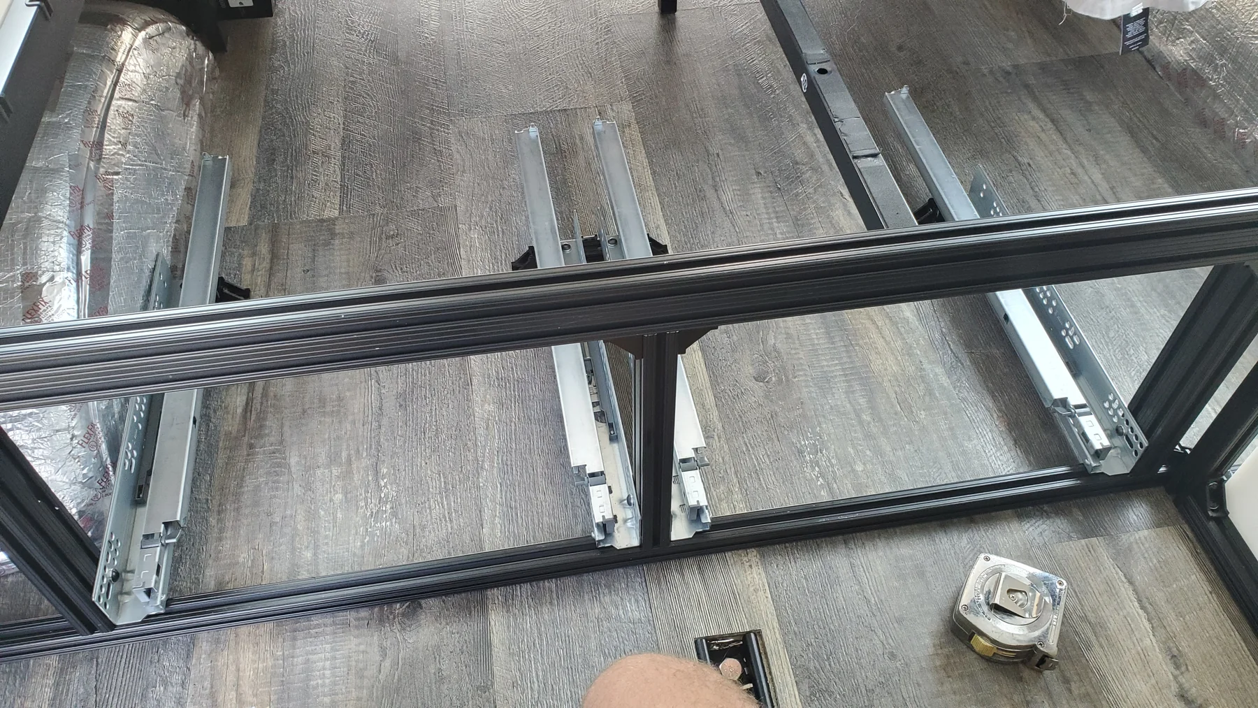
The April 2021 photographs show the black slotted frame with its drawer bays exposed. Crossmembers divide the space; low hardware runs beneath the future boxes. With the drawers absent, it is possible to see clearances that the completed interior hides.
For your own platform, draw the clear openings as well as the outside frame. Connectors, crossmembers, slides and floor contours all reduce usable space. Include the actual bearing surfaces for the slats and the route by which the intended load reaches the vehicle.
The photographs are not a structural calculation. Profile choice, joint configuration and vehicle attachment require a design appropriate to the load and vehicle. A kitchen frame or drawer bay should not be assumed to provide an adequate bed support simply because it fits beneath the mattress.
Planning step
3 / Preserve access through the sleeping surface
Michael’s equipment record describes removable slats. The finished rear photograph shows pale slats above the dark frame. This arrangement makes the bed surface and the storage frame distinct parts of the assembly.
When designing a removable surface, record how the slats are supported, located and retained. Decide which parts can be lifted for service and whether a mattress must be removed first. Include the edge supports and any intermediate bearings in the drawing.
Slat material, span, spacing and retention details are not established here as a repeatable specification. Moisture management below the mattress also needs its own consideration; visible gaps do not prove a particular condensation or ventilation performance.
Photographed stage
4 / Reserve the whole drawer movement
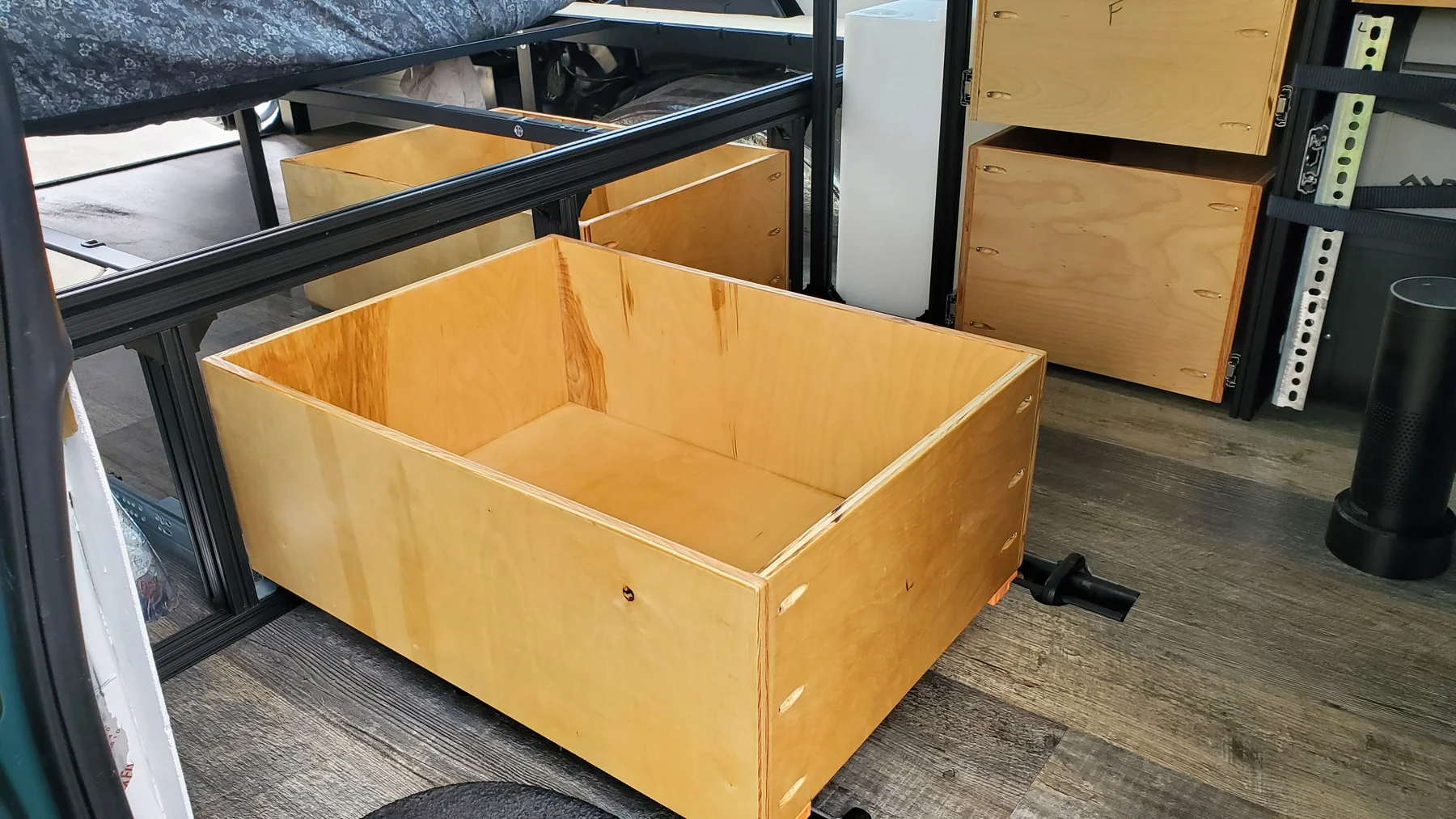
The next-day drawer photographs show two plywood boxes fitted into the lower bays. One image shows a box extended into the aisle; the neighboring box and kitchen remain visible. The travel envelope is part of the living-space layout, not just the bed drawing.
Before finalizing the platform, open each proposed drawer with adjacent seats and doors in their intended positions. Check hand access to the contents and whether another drawer must be closed first. The drawer guide follows the photographed runner-to-box sequence and includes a width-planning tool.
Planning step
5 / Keep a service route through the rear
From the rear doors, Walter’s finished garage has a central support and the backs of the two large drawers. Wiring and equipment occupy surrounding areas. The photograph is useful because it shows the clearance remaining after the storage boxes are installed.
Plan a route to inspect the equipment below the bed without dismantling the entire interior. Keep controls, isolation points and service labels visible where their manufacturers require access. Include cable and hose protection wherever equipment shares the storage space.
Record which panels, drawers or slats must be removed for each service job. That map will matter later, when a component needs attention away from the workshop.
Before the mattress becomes the finish
- Check sleeping clearances using the actual mattress.
- Confirm intended load paths, connections and vehicle attachments through the completed platform.
- Operate loaded storage through its full travel and verify travel retention.
- Check slat support, fit and retention against the actual design.
- Rehearse access to electrical, water and other service equipment.
- Photograph the frame, joints and service routes before covering them.
Walter demonstrates how a bed can organize sleeping, storage and systems in one compact footprint. For another conversion, transfer that planning method and measure the actual vehicle rather than copying dimensions from perspective photographs.
About these notes
Original frame, runner, drawer and finished-garage photographs; Michael’s record identifies a full-size bed and removable slats. Drawings are explanatory, with no invented frame cut list, mattress dimensions, structural rating or attachment schedule.