Planning step
1 / Design the openings before the members
The useful result of a furniture frame is the space it creates: a bed surface, a drawer opening, an appliance bay or a removable service panel. Start with those finished requirements, rather than dividing the van into a grid of attractive-looking rails.
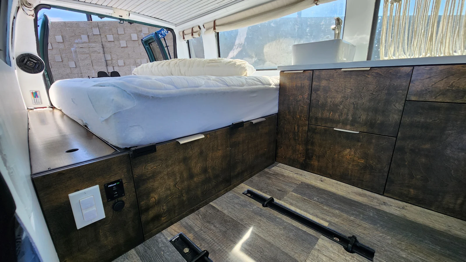
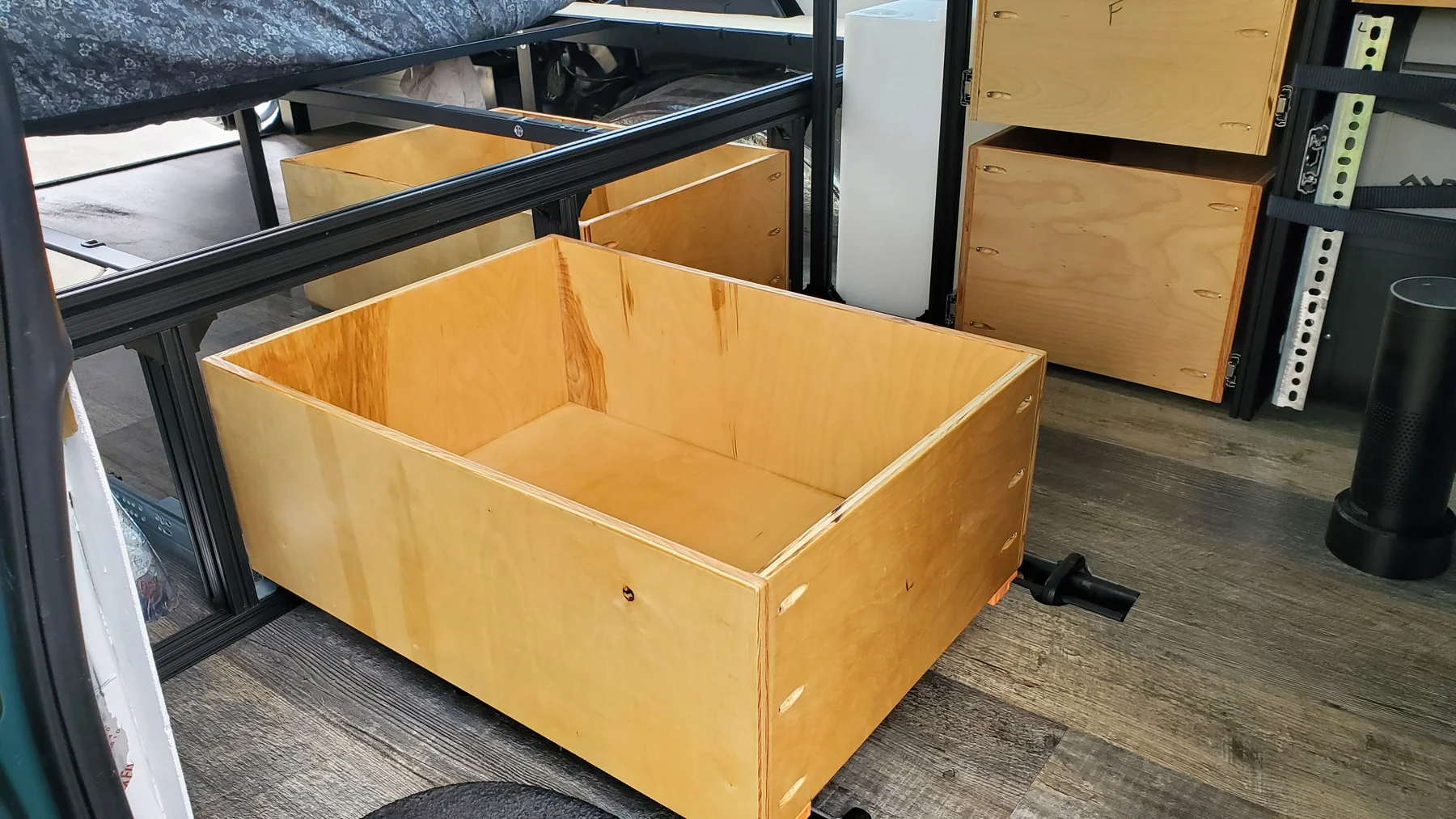
Walter’s exposed bed framing makes this clear. Two drawer bays sit below the sleeping platform, with rear access to the surrounding garage. A member can be in the right place for the mattress and still obstruct a drawer, a locking component or the hand needed to release it.
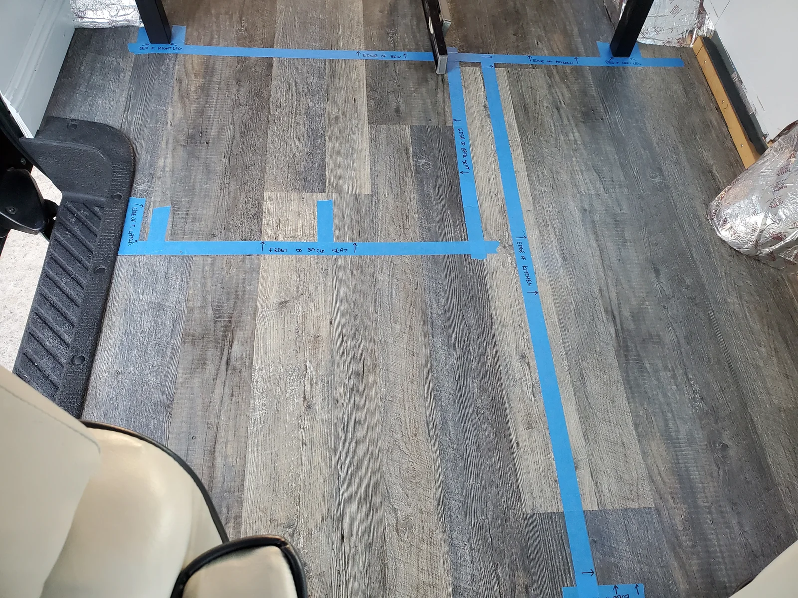
Draw the outside envelope, the clear openings and the equipment movements separately. Mark which dimensions belong to the frame, which belong to the finished lining and which are allowances required by exact hardware.
Planning step
2 / Identify the actual profile and compatible hardware
A July 2020 photograph shows loose slotted extrusion stock. Its final assignment is not established; it is not used as proof that a particular length became a roof rail or a furniture member.
Purchase records include 80/20 profile candidates, while installed photographs show black slotted framing. That combination still does not establish every finished member’s series, dimensions or part number. A shopping record and an installation photograph answer different questions.
For your own frame, keep the supplier’s exact profile drawing, compatible connector list and required assembly instructions together. Slot appearance alone is insufficient for choosing a nut, connector or load-bearing joint.
Planning step
3 / Resolve the joint as well as the span
List what each joint must connect, the directions of expected loads and how it attaches to the surrounding vehicle or furniture. Include the connectors, fasteners, access for assembly and the instructions for the chosen system.
Walter’s visible members explain the geometry, but the photograph does not expose every hidden connector or establish a tested load rating. A complete design needs the actual spans, loads, joints and attachments; the outside appearance is only part of the record.
Keep the frame drawing and the vehicle attachment drawing coordinated. A stiff furniture module still needs an appropriate connection to its vehicle, and an accessible joint before lining may become unreachable after the bed or counter is installed.
Planning step
4 / Record repeatable fabrication setups
An August 2020 photograph shows a metal plate held in a pocket in a timber fixture beneath a drill press. It is a useful example of documenting a setup, but the final purpose of that plate has not been established.
A fabrication record can identify the part, its reference edges, hole locations and orientation before a repeated operation begins. Keep that record with the part drawing, selected tooling and the equipment’s operating instructions.
This photograph is not a drilling procedure or a dimensioned production template. For another build, the actual material, hole specification, tooling and workholding need to be resolved for the part being made.
Planning step
5 / Trial-fit the complete moving assembly
Check the frame with the neighboring parts present: runner bodies, drawer boxes, locking hardware, fronts, bed slats and finished floor. An empty opening can conceal conflicts that appear only when the hardware is mounted.
Walter’s drawer sequence and width worksheet keep the measured opening separate from the outside box width and visible front. Hardware-specific allowances belong in that calculation before the members are cut.
Move each assembly through its travel and confirm removal access. Do the same for nearby equipment such as the cooler or water container. Record adjustments before finished faces hide the reference points.
Leave the next repair a usable record
- Identify installed profile series, lengths and orientations.
- List exact connectors, fasteners and their matched assembly instructions.
- Record spans, intended loads and the resolved vehicle attachments.
- Dimension clear openings after finished lining and hardware allowances.
- Demonstrate drawer, appliance and service-component removal.
- Photograph accessible joints and label removable panels before closing the frame.
Slotted framing can make the relationships easy to see and revise during planning. Walter’s example is most useful when those relationships travel to another campervan alongside its own measurements and a fully resolved design.
About these notes
The archive shows loose slotted extrusions, a separate drilling fixture and installed bed/drawer framing. These are distinct views, not a proven continuous manufacturing sequence. Exact installed profiles, joints, fasteners and structural ratings remain unresolved.