A useful sequence: opening, hardware, box, front
Walter’s under-bed drawers turn a deep storage area into something accessible from the aisle. The strongest construction photographs show the system before the boxes are fitted: the frame openings and runner assemblies remain exposed.
The following day, the plywood boxes are in place. Pocket-hole joinery is visible on their faces, and a later finished photograph shows the drawers in everyday use. This is enough to explain a valuable sequence without inventing panel thicknesses, runner ratings or concealed fasteners.
For another campervan, choose the hardware before finalizing the box. A drawer that fits the opening geometrically still needs the right bottom details, connector positions, travel and retention.
Photographed stage
1 / Choose the mounting geometry first
The exposed metal runners sit low in Walter’s bays, with the drawer supported from below. This is visibly different from a conventional side-mounted slide fitted to the drawer wall. The photographs do not yet establish the exact runner model or its rated load.
Purpose-designed undermount hardware has specific requirements for drawer side/bottom geometry and locking devices. Turning an ordinary side slide onto its flat face does not create the same system. Use the exact model’s technical sheet, including permitted mounting orientation, clearances, fixing points and adjustment.
Accuride’s application guidance, as a general manufacturer reference, emphasizes mounting geometry, parallel alignment and shock/vibration conditions. It is not an identification of Walter’s hardware or a load rating for it.
Planning step
2 / Measure the completed opening
Measure between the finished mounting faces at the front, middle and back. Check height and diagonals as well as width. A frame that tapers or twists can let an empty box slide in while binding under load.
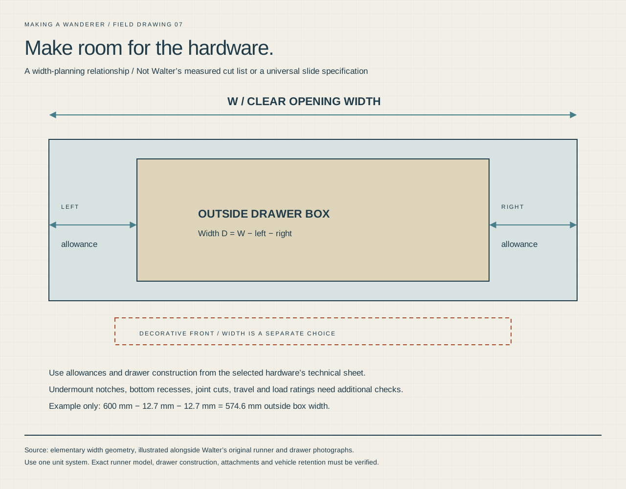
Record the smallest usable width, the chosen runner allowances and the obstructions at the rear. Include bolt heads, brackets and floor contours. For side-space planning, the simple relationship below is useful. An undermount model may also define drawer inside width, bottom recesses and notches; its complete instructions still govern.
 Enlarge drawing ↗
Geometry worksheet
Make room for the hardware
The relationship between opening width, side allowances and outside drawer width, with the front treated separately.
Download sharp vector drawing ↓Try a drawer-width plan
Enter one unit system throughout. Use clearance allowances from your selected hardware’s instructions. This calculates the outside box width between those allowances; it does not determine drawer fronts, panel cuts, undermount recesses, load capacity or attachment design.
Example only
A 600 mm opening minus 12.7 mm on each side leaves 574.6 mm for the outside box. Those example allowances are not a specification for Walter’s runners or a universal drawer clearance.
Photographed stage
3 / Fit the box before committing the front
The April 11 photographs show two large plywood boxes in the frame. Their visible pocket holes record part of the joinery, while the open tops make the internal storage volume easy to inspect.
For your own build, derive panel cuts from the selected joint, material thickness and bottom construction. Check squareness and hardware interfaces before attaching a decorative front. The visible pocket holes do not establish a complete joint schedule, adhesive choice, panel grade or drawer load rating.
Fit and cycle the box first. Then work out the front overlay or inset, handle position and gaps between neighboring fronts. The box width, outside face width and clear access opening are different measurements.
Photographed stage
4 / Test travel where the drawer will actually be used
An extended box occupies space that is normally part of the aisle. Walter’s construction photo shows the drawer beside the kitchenette, with its tall sides and open top visible. The finished photographs show cookware and other supplies being brought into reach.
Check the complete movement with the intended contents in place. Confirm that a person can stand or kneel beside it, lift out the largest item and put it back. Check doors, seating, cabinet handles and other drawers throughout the same movement.
Travel retention needs to be verified separately from soft-close action. Document the closure/locking arrangement and the hardware’s suitability for the intended loads and vehicle movement. A smooth empty-drawer demonstration does not establish either.
Planning step
5 / Finish for maintenance, then organize for use
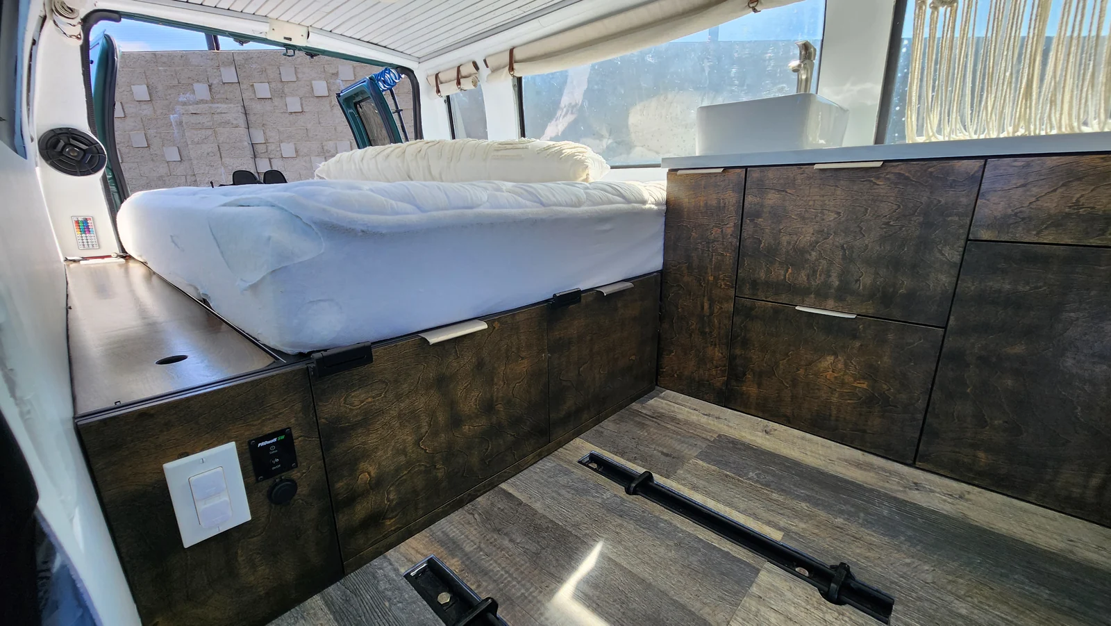
Walter’s finished dark fronts make the drawers part of the interior, while the light box interiors keep their contents visible. Separating the serviceable box from the decorative front makes adjustment easier to understand.
Choose a finish suited to the actual panel and intended use, keeping moving hardware free of overspray or buildup. Leave access to disconnects and adjustment points. Keep the drawer removal instructions with the build record so a runner can be serviced without guessing at hidden clips.
Organize around the things that need frequent access. Heavy cookware, small tools and soft goods create different movement and retention needs. Dividers and liners should help those jobs while still allowing the box to be cleaned.
A drawer is finished when the whole routine works
- Measure front, middle and rear opening geometry.
- Confirm the exact runner model and all its drawer-construction requirements.
- Cycle the fitted box before setting the decorative front.
- Check full travel with the intended contents and neighboring furniture.
- Verify retention for the intended vehicle use.
- Demonstrate drawer removal, hardware inspection and adjustment access.
The payoff is access. Walter’s drawers turn storage from a space to crawl into, into something that comes to the living area. The same principle applies across campervan layouts, provided the dimensions and hardware are designed for the actual build.
About these notes
Original April 2021 runner/box photographs and July 2025 finished-storage views. Purpose-built runners are visible below the boxes, but their exact model/rating is unresolved. The planner calculates width geometry only; it is not Walter’s cut list or a slide-installation specification.