A system you can actually follow
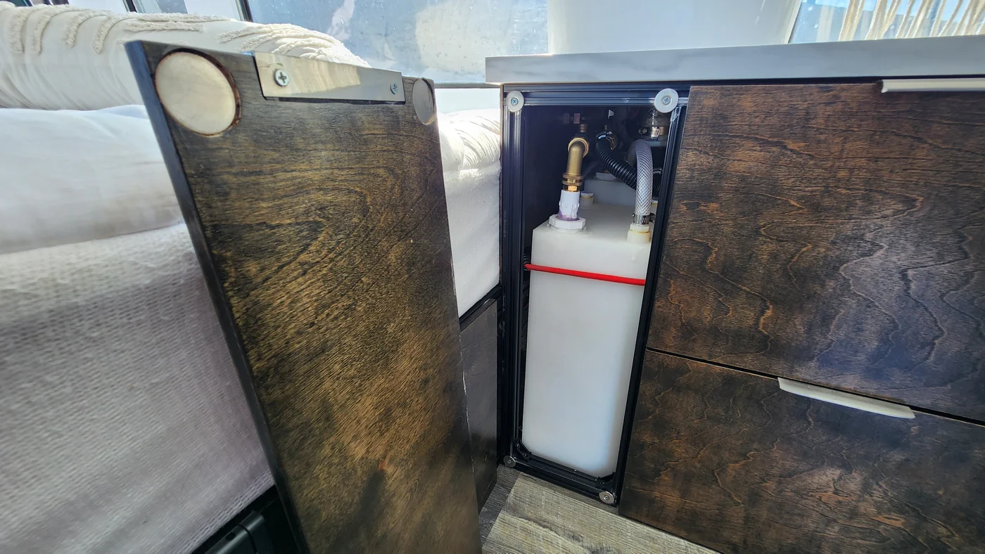
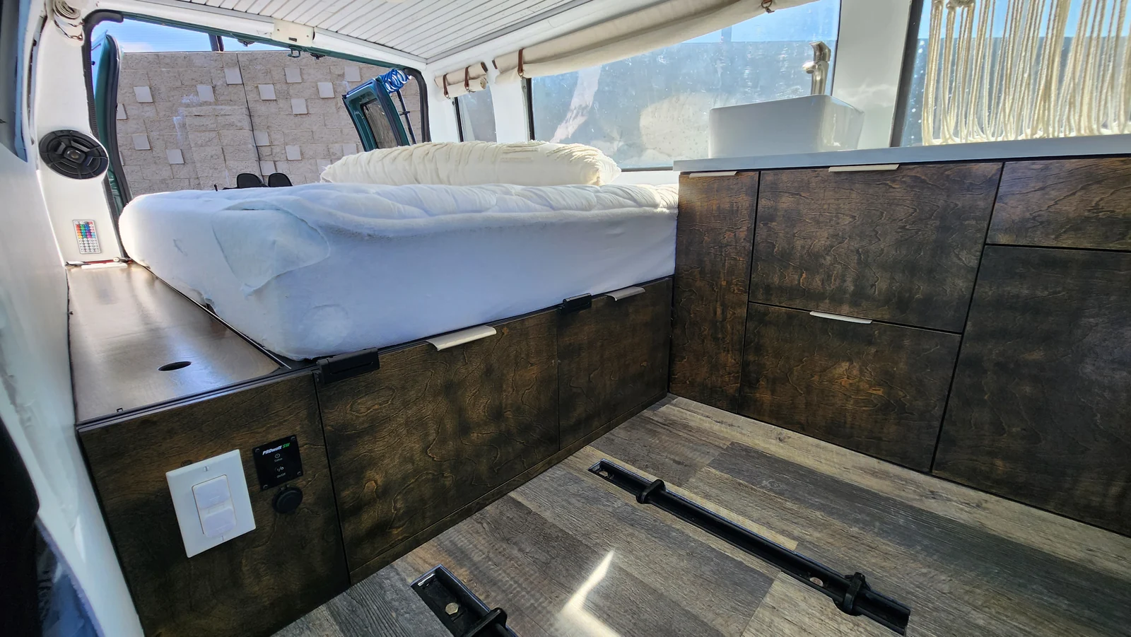
Walter’s equipment lives beneath the bed, with controls accessible through the rear of the van. Solar generation, stored energy, vehicle charging, a DC distribution panel and an inverter share this compact service area.
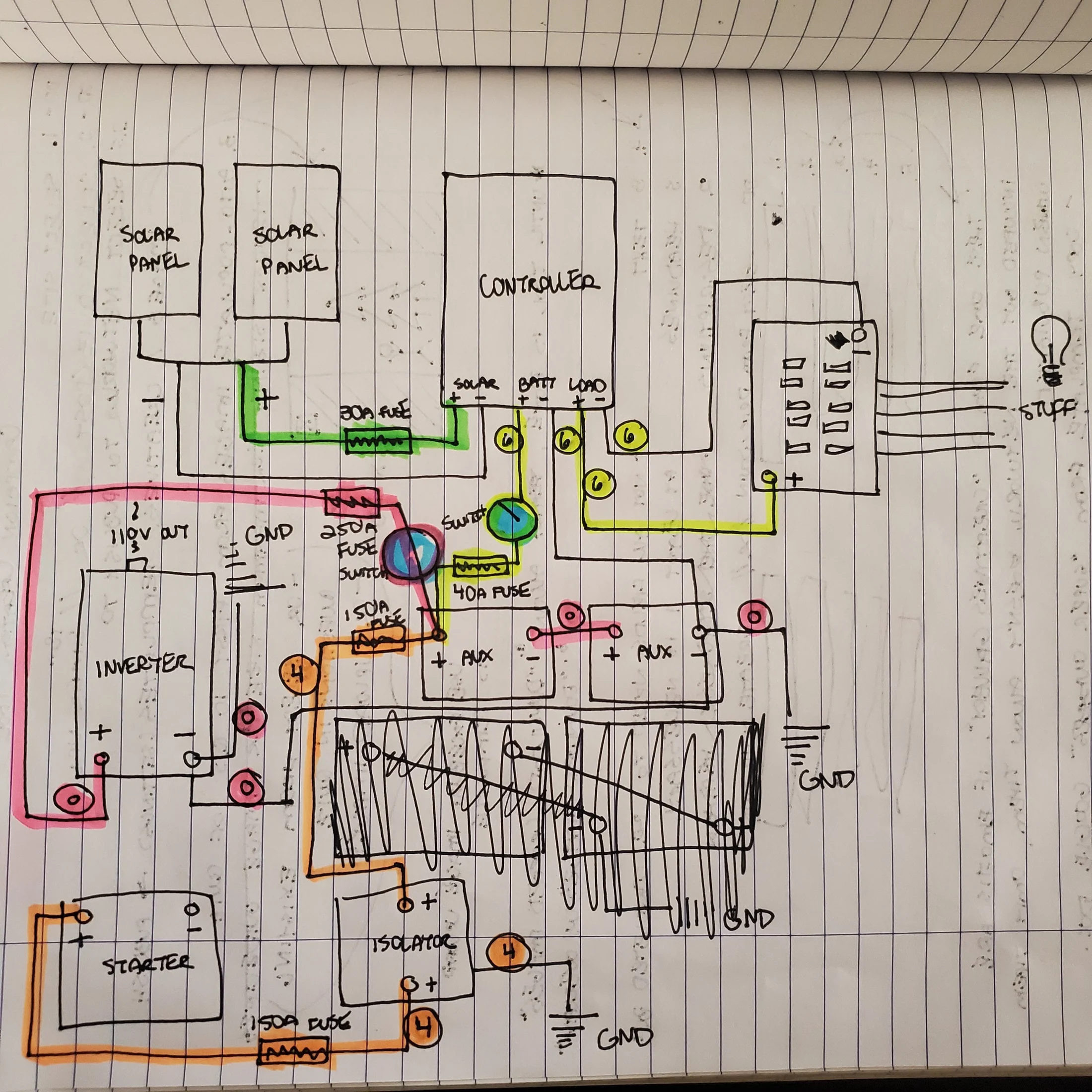
The starting point is Michael’s October 2020 notebook. He has confirmed that it still describes the finished DC wiring. A clean redraw makes those paths readable, while original photographs and equipment labels keep the explanation tied to this particular build.
There are two different jobs here: documenting Walter faithfully and designing a system for another van. The notebook answers many questions about the first. A new installation still needs its own load budget, cable lengths, component instructions and protection design.
Read the labels before adding the numbers
| Function | Identified equipment | Basis and remaining detail |
|---|---|---|
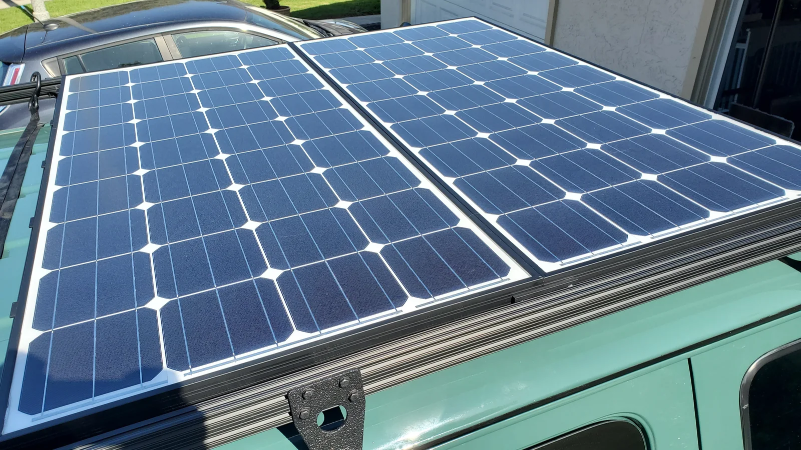
| Solar generation | 2 × 180W Hightec panels; photographed label RCL-M-180 | The pair is in the owner record; one model label is photographed. Internal array series/parallel arrangement is unresolved. |
| Solar regulation | EPEVER TRIRON4210N, 40A MPPT | Model legible in the November 2020 installed-controller photograph. |
| House battery storage | 2 × EnergyPower/Vision EP-EVGC-220A-AM, 6V 220Ah AGM | Label photographs identify voltage/capacity; the notebook shows the series jumper. |
| Vehicle charging | Battery isolator, connected between starter and house positives | Topology shown in the notebook; exact isolator model and operating behavior still need matching. |
| DC distribution | Blade-fuse panel connected to controller LOAD terminals | Source labels the outgoing circuits “STUFF”; individual circuits and fuse values are not named. |
| Inverter | Xantrex PROwatt, recorded as 2000W | Owner equipment record; exact inverter variant and its complete installed AC arrangement remain open. |
| AC battery charging | NOCO GENPRO 10X1 | Identified in a July 2025 label photograph; not a vehicle DC-to-DC charger. |
| AC source selection | Xantrex transfer switch 808-0915 | Photographed label: 120V, 60Hz, 15A maximum. Concealed wiring is not established by the exterior label. |
A nameplate identifies a component. It does not demonstrate its settings, present condition, measured output or every cable connected behind it.
The finished DC notebook, redrawn
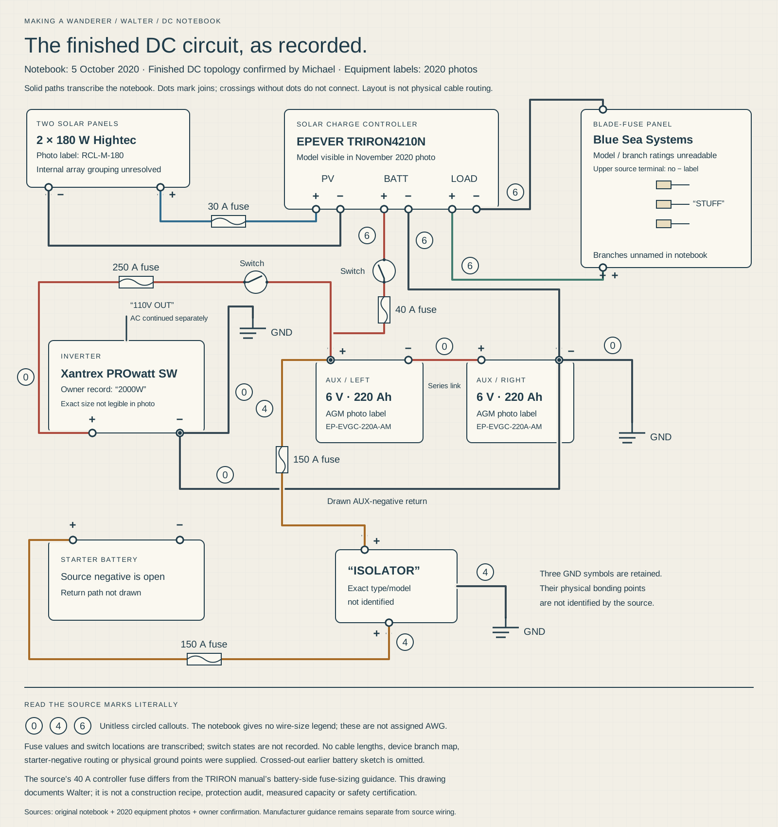
Follow the positive paths from the solar array, starter battery and house bank. Then follow each return independently. The redraw retains the source’s controller terminal groups, switches, fuse labels, battery jumper and separate ground symbols.
The handwritten 30A, 40A, 150A and 250A values are transcribed historical values. The circled 0, 4 and 6 are retained as unitless source callouts because the page does not provide a wire-unit legend. Neither set of labels substitutes for cable and protection sizing.
Connections that were crossed out on the notebook are excluded from the active redraw. The two photographs of the same sheet have different orientations; they are not separate design revisions.
 Enlarge drawing ↗
Notebook wiring redraw · source values
Walter’s finished DC wiring
A source-faithful redraw of the owner-confirmed October 2020 notebook. Handwritten fuse values and unitless cable callouts are preserved; suitability, cable units and individual load circuits require verification.
Download sharp vector drawing ↓1 / Solar: array, regulator, battery
The notebook brings the array positive through a labelled 30A fuse into the controller’s SOLAR positive terminal, with array negative returning to SOLAR negative. The grouped array symbol does not resolve the internal panel-to-panel connections, so the redraw leaves that choice open.
The controller’s BATT positive path passes through a drawn switch and a labelled 40A fuse to the auxiliary-bank positive node. BATT negative returns to the bank’s negative side as shown. Keep this battery connection distinct from the controller’s LOAD terminals, which serve a different circuit in the source.
Two 180W panels give a combined nameplate rating of 360W. That is a rating, not continuous production: orientation, shade, weather, temperature and charge state affect what reaches the bank. Likewise, “40A” identifies the controller’s class; it is not a claim that every terminal or connected load has that allowance.
2 / Two 6V batteries make one 12V bank
The battery labels resolve an ambiguity in the equipment list. Each photographed battery is rated 6V, 220Ah. The notebook joins the negative of one battery to the positive of the other, leaving the outer positive and negative as the bank terminals.
Series arithmetic
6V + 6V = nominal 12V. The series bank remains 220Ah. Nominal energy is 12V × 220Ah = 2,640Wh before discharge limits, conversion losses, age, temperature and actual battery condition are considered.
Adding the two amp-hour labels to make 440Ah would describe a different connection. Neither the nameplate calculation nor the photographs establish usable capacity or how long an appliance will run.
For a new design, record the intended daily watt-hours and each large load’s operating and startup demand. Reconcile those needs with the actual battery instructions, charging equipment, protection and cable routes. Keep battery service access and the ability to identify each conductor in the layout from the beginning.
3 / Vehicle charging is its own path
The notebook links the starter-battery positive and the house-bank positive through a battery isolator. A separate 150A fuse is drawn on each side of that connection. The isolator has its own GND symbol.
The starter-battery negative is drawn as a terminal without a completed return line. The redraw preserves that source limit. It does not invent a chassis cable route or assume that every ground symbol identifies one physical stud.
The exact isolator model, its control behavior, alternator characteristics and cable runs remain unverified. This historical arrangement is not a general endorsement for a different alternator or battery chemistry. An isolator and a DC-to-DC charger perform different jobs; a product choice needs to match the vehicle and battery requirements.
4 / Read the DC distribution path literally
The blade-fuse panel is fed from the controller’s LOAD positive and LOAD negative terminals in the notebook. The negative feed is drawn separately from the controller’s battery return. These terminal groups remain separate in the redraw so the documented circuit is understandable. The manufacturer describes a common-negative controller; separately drawn leads do not imply electrically isolated returns.
The outgoing circuits are simply labelled “STUFF.” The owner record describes 12V outlets, but the notebook does not identify each outgoing circuit, its fuse, cable length or load. The drawing therefore does not assign a pump, light, fan or refrigerator to a particular fuse position.
A useful circuit schedule for another conversion records the appliance, continuous/startup current, supply terminal, complete conductor route, length, conductor specification, fuse and disconnect. Check the controller’s exact load-output behavior and rating before deciding whether an appliance or distribution panel belongs there. Do not treat the solar charging rating as a branch-load rating.
5 / The inverter has a separate heavy-current feed
The source shows house positive passing through a main switch and a labelled 250A fuse to inverter positive. Inverter negative returns to house negative. A separate branch from the source’s inverter-negative path terminates at a GND symbol; the redraw retains the symbol without converting it into an invented mounting point.
The inverter block is annotated “110V OUT.” That handwritten label is preserved as a source note. It does not specify the outlet branch circuit, protection, transfer wiring or grounding arrangement.
Inverter sizing needs both the actual appliance demand and the inverter’s own instructions. On the DC side, high power at a low voltage means substantial current. Cable length, conductor material, terminations, temperature, installation method and fault protection all matter. Walter’s historical 250A label is evidence of his notebook, not a universal fuse recommendation for a 2000W inverter.
Shore power: the equipment and the remaining wire trace
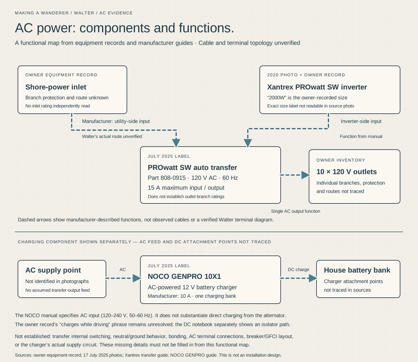
The equipment record identifies a shore inlet and a transfer switch. Later photographs identify a NOCO GENPRO 10X1 battery charger and Xantrex transfer switch model 808-0915. The AC drawing organizes those components by function and distinguishes verified identities from relationships that still need tracing.
The NOCO is an AC-powered battery charger. It should not be described as the device that charges the bank while driving: the notebook’s isolator path is the documented vehicle-charging route. The owner record’s wording about onboard charging needs this distinction.
The exterior transfer-switch label does not prove the connected source priority, receptacle circuit routing, neutral/ground arrangement, protection or every terminal connection. The October notebook is a DC drawing. A complete terminal-level AC schematic still needs an installed-wire trace and the exact inverter instructions; the functional map does not fill those gaps with assumptions.
 Enlarge drawing ↗
AC functional study · trace still needed
Shore, inverter and AC charging
Identified AC components and their functions, with concealed terminal routing and grounding left unresolved. This is a functional study, pending an installed-wire trace.
Download sharp vector drawing ↓Compare the record with the manufacturers’ instructions
The EPEVER TRIRON manual identifies the TRIRON4210N’s rated charge and discharge current as 40A. It specifies battery, then load, then PV connection order, with the reverse disconnection order, and puts an inverter directly on the battery rather than the controller’s LOAD output.
There is also a protection detail to resolve before this historical drawing could become an installation specification: the manual gives a battery-side fuse range of 1.25–2 times rated current, within 150 mm of the battery. That differs from the notebook’s 40A annotation for this 40A controller. The redraw preserves the annotation and flags it for review; it does not silently replace Michael’s record or approve the old value.
NOCO’s GENPRO10X1 specifications identify an AC-input, single-bank 10A charger. The Xantrex 808-0915 guide describes inverter and utility/shore inputs serving one AC output circuit, with a 15A maximum rating. That describes product function; Walter’s hidden source/output routing still needs tracing.
These references clarify the identified equipment. They do not establish installed settings, code compliance, cable suitability or the condition of the completed system.
Keep the original beside the redraw
The notebook shows how Michael thought through the build: colored paths, grouped components and crossed-out alternatives. Compare it with the redraw when a symbol or connection needs context.
The public copy contains the engineering page, without private account records or equipment serial-number photographs. Equipment identities are transcribed into the chapter instead of publishing raw label images that carry unrelated identifiers.
Save the original notebook photographWhat makes this useful for another conversion
Start with the same systems questions, then answer them for the van being built. Which loads are DC? Which require AC? How much energy is needed each day? Where will charging come from? Which equipment can be reached for inspection without dismantling the bed?
- Build a load schedule with expected use and startup demand.
- Match batteries and charging equipment to the vehicle and intended operation.
- Draw positive and return paths, disconnects and every protection point.
- Record actual cable routes and lengths before final conductor/protection selection.
- Resolve all AC source selection, outlet protection and grounding details against the installed equipment instructions.
- Label the installed circuits and retain settings, manuals and dated photographs.
- Have the completed design and installation checked by a qualified person before energizing it.
For Walter, the DC topology is owner-confirmed and the redraw is source-based. Individual load circuits, cable units/lengths, protection suitability, settings and hidden AC wiring still need independent physical or engineering verification. Those are specific remaining checks, rather than details a neat drawing can establish.
Explore the system photographsAbout these notes
Michael confirmed in October 2026 that the October 2020 notebook still describes the finished DC wiring. Equipment labels add model and voltage information. The redraw preserves the source’s connections and handwritten fuse values; it is not a new engineered installation specification. Unlabelled branches, cable units, hidden protection and AC terminal details remain explicit gaps.