Treat the roof as a system of interfaces
Walter’s roof brings two solar modules into a rack made with dark slotted members and mounting hardware. The September 2020 photographs are particularly useful because they look at the rail ends and underside, where the finished side profile reveals very little.
The useful questions extend beyond fitting a panel into the available space. Where does each load travel? Which joints can be inspected? How will a panel or cable be serviced? What is the real vehicle and equipment limit for the intended use?
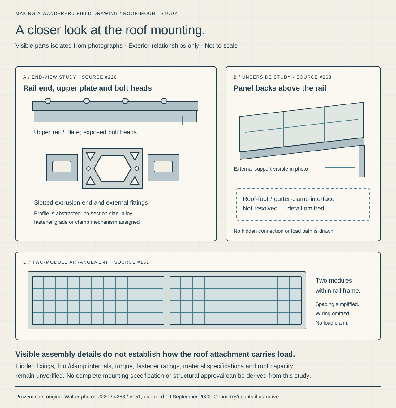
The drawing highlights the visible relationships and leaves concealed roof-foot details unresolved. It documents this build without turning a photograph into a structural calculation.
 Enlarge drawing ↗
Visible-interface study · incomplete mounting design
The visible roof-mount interfaces
Extrusions, plates, bolt heads and panel backs are shown from photographed views. The unresolved roof foot and structural load path are deliberately omitted.
Download sharp vector drawing ↓Photographed stage
1 / Preserve the fabrication record
A September 12 image shows loose bent pieces and flat plates, with varied hole patterns and surface marks. It gives a useful view of the hardware before assembly hides portions of it. The photographs do not identify the function of every piece or prove that all of them reached the final roof.
For a new fabrication, retain the drawing, material specification, hole locations and intended joint function. Keep test pieces and inspection records where they matter to the design. A collection of similar-looking plates is not a verified parts list.
Walter’s broader workshop archive also contains slotted extrusion stock and a plate in a drill-press fixture. Their final assignments are unresolved, so they remain separate fabrication studies rather than a roof-rack cut list.
Photographed stage
2 / Inspect the actual rail-end connection
The September 19 close-up exposes a slotted crossmember end, end hardware, an upper member and a textured plate with bolt heads. These views explain how much of a joint disappears from a distant photograph.
In another design, specify the profile and connection as a pair. Check the hardware’s access, bearing surfaces, engagement and inspection route using the actual manufacturer information. Include the intended dynamic vehicle conditions in the engineering review.
The photograph does not establish fastener grade, torque, preload or structural adequacy. The visible head shape alone cannot supply those details.
Photographed stage
3 / Follow the assembly beneath the modules
A second angle shows panel backs, nearby cables and a support reaching toward the roof gutter. It is a useful service view: equipment that appears flat and tidy from above still has an underside that needs inspection.
Plan access for connections and fixing points before placing the panels. Check the actual cable route, contact with edges and movement at joints. Use component instructions to resolve fixing zones and separation requirements.
The shallow-focus source does not reveal the complete roof foot or cable connections. The drawing therefore stops short of inventing a gutter clamp, hidden seal or attachment rating.
Photographed stage
4 / Check the pair as a complete roof assembly
The top view shows two glass-front modules side by side within the rack rails. The owner equipment record identifies two 180W Hightec panels, and a separate photographed label identifies the RCL-M-180 model on one module.
Check panel placement together with ventilation, other roof equipment, service access and the vehicle’s actual height. Account for the intended loads and operating conditions in the design. A generous-looking rack area does not establish a safe standing surface or spare carrying capacity.
The photograph does not settle the array’s internal series/parallel wiring. The electrical guide preserves that separate source question while tracing the confirmed DC notebook.
Keep the mechanical and electrical records connected
Retain an installed-parts record with the profiles, joints, panel model, roof attachments, cable entries and inspection access. Photograph both the top and the underside. Record the hardware requirements from the selected products and the completed checks from the actual installation.
- Verify vehicle, rack and equipment limits for the intended use.
- Resolve the complete load path, including concealed roof attachments.
- Keep required fixing zones and service access clear.
- Record fastener specification and tightening requirements from the design/manufacturer.
- Trace and protect the actual cable routes.
- Have the mounting design and completed installation checked before road use.
The most transferable lesson from Walter’s detail photos is to preserve the joints, routes and access while they can still be seen.
About these notes
Original roof photographs show two modules, slotted rails, bolt heads, plates and an underside support. Separate workshop views show stock, a drilling jig and loose hardware; not every piece is proven to be part of the final roof. No load rating, torque, fastener grade, complete gutter-foot design or panel electrical grouping is inferred.