The fan is only part of the installation
A roof vent is a visible product attached to a less visible detail: an opening through a shaped metal roof. The photographs show the part that is easiest to miss in a finished tour—the preparation around that opening, the temporary clamping and the receiving flange before the fan covers it.
An archived label identifies Walter’s fan as a MAXXFAN Deluxe 7500K. The selected work photographs are dated May 20, 2018. They provide a sequence to study, while the matching manufacturer guide provides the installation requirements.
 Enlarge drawing ↗
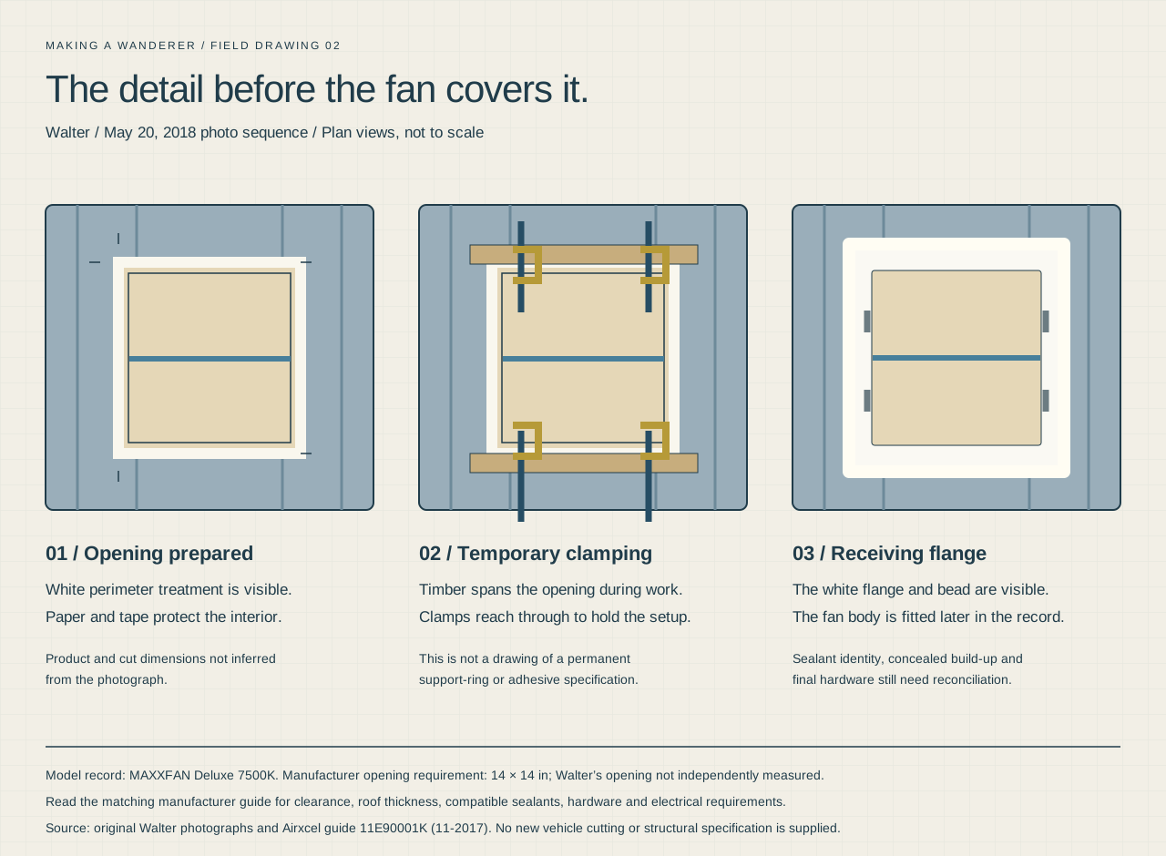
Photo-based detail drawing
Before the fan covers it
Three photographed stages explain the roof opening, temporary clamping and receiving flange.
Download sharp vector drawing ↓Start with the correct reference
Airxcel’s MAXXFAN Deluxe installation and operating guide includes the 7500K. It specifies a 14 × 14-inch roof opening, clearance of at least 8 inches behind the flange’s rear edge, roof thickness from 1⅛ to 6½ inches, and a minimum 12V DC, 5A service. These are manual requirements, not measurements or operating-current tests of Walter.
Use the manual for sealant compatibility, mounting hardware, electrical connections and trim. The visible white material in the build photographs is not enough to identify the product used.
About the drawing
The roof-detail illustration follows the photographs and distinguishes the temporary clamping stage from the receiving flange. It does not supply a new sealant specification, fastener pattern or vehicle cutting approval.
Photographed stage
Study the opening and interior protection
The first selected photograph shows an opening already cut in the blue roof, with marks around its perimeter and a white treatment around the exposed area. Brown paper and blue tape protect the interior below.
The cutting itself is not shown in this selected sequence, so we are not inventing a tool, blade or drilling pattern. The useful detail is the relationship between the opening and the nearby roof ribs, together with protection beneath the work.
For another vehicle, establish the opening location against the actual roof structure and the fan’s clearance requirements before cutting. A photograph of Walter cannot establish what lies beneath a different roof skin.
Photographed stage
Look at the temporary clamping arrangement
Timber pieces span the opening while clamps reach down through it. The photo preserves both the top surface and the work being held below. A loose white trim piece sits nearby, outside the opening.
The spans and clamps are part of the work-in-progress setup. They should not be mistaken for a drawing of the final roof assembly. The photograph does not establish the timber species, a permanent support-ring design or the adhesive being held.
This distinction is why the detail drawing shows the clamping stage on its own. A convincing illustration should explain the evidence without quietly making temporary tools into permanent structure.
Photographed stage
Check the perimeter before it disappears
A later photograph shows the opening without the long clamp bars. Small white blocks remain visible beside the opening, with green tape at the edges. The white perimeter treatment can still be seen.
These are details worth photographing before a flange covers them. Their dimensions and final role have not been confirmed, so the drawing labels them as photographed blocks rather than assigning them an unverified structural function.
Photographed stage
Inspect the receiving flange
By 3:25 PM in the camera record, the white receiving flange sits around the opening. Its metal clips and the perimeter bead are visible. The fan body is photographed in place later that afternoon.
The flange image shows what the final product shot hides: the shape of the perimeter and how the receiving component relates to the opening. It cannot prove that every concealed fastener, seal or connection was completed correctly.
A completed guide for reproducing this installation still needs the exact products and the finished mounting build-up reconciled. Until then, use the manufacturer guide for installation specifications and this sequence for understanding Walter’s recorded work.
Keep the installation inspectable
- Keep the fan model and its matching manual in the build record.
- Document the opening and concealed build-up before fitting trim.
- Leave the interior trim removable for later inspection and service.
- Record the actual sealant products and hardware instead of relying on a finished photograph.
- Inspect the completed installation for water entry and mechanical operation; the archive does not document a repeatable test result.
The roof fan is a good example of the work behind Walter’s clean finish. The care sits in the interfaces between parts, not just in choosing the product.
Common questions
Is the 14-inch opening measured from Walter?
It is the requirement in the model-matched manufacturer guide. We have not independently measured Walter’s cut-out from the original vehicle.
Can the white perimeter material be identified from its appearance?
Not reliably. The source record still needs an exact product match. Color alone is not a sealant or compatibility specification.
Are the long wooden pieces permanent?
They are visible in the temporary clamping setup. The selected photographs do not establish that those spans remain in the final installation.
About these notes
Original photographs from May 20, 2018, plus the archived model label and Airxcel’s MAXXFAN Deluxe guide. The photographic sequence is separate from the manufacturer’s installation requirements.