Four jobs beneath your feet
A van floor has several jobs at once: cover the uneven metal shell, separate the living space from the floor beneath it, provide a surface for everyday use, and fit around the wheel wells and doors. Walter’s photographs are especially useful because they show the floor before furniture hides its edges.
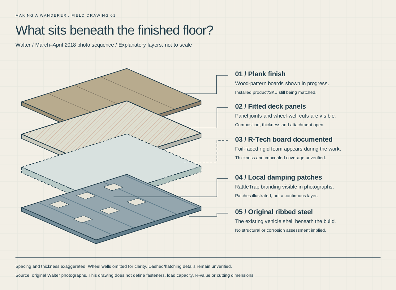
The sequence starts with the exposed blue metal floor and ends with staggered wood-pattern planks. In between are localized damping patches, foil-faced insulation pieces and pale deck panels. The drawing below separates those visible stages so each job is easier to understand.
 Enlarge drawing ↗
Photo-based assembly study
The floor, layer by layer
An exploded view of the documented floor stages, with unknown materials and thicknesses kept visible.
Download sharp vector drawing ↓The materials we can identify
| Item | What the record establishes |
|---|---|
| Original steel floor | Visible ribs, wheel wells and factory openings. The photographs do not establish a structural inspection or a complete corrosion-treatment specification. |
| Sound damping | RattleTrap branding is legible on the small foil-faced patches. The recorded coverage is local patches, rather than a continuous blanket. |
| Insulation | R-Tech branding is legible on rigid foam board photographed during the work. Exact board thickness and concealed coverage are not yet confirmed. |
| Deck panels | Pale panels are fitted around the wheel wells. Panel composition, thickness and attachment schedule still need a source match. |
| Floor finish | Wood-pattern planks are shown partly installed. A separate shopping photo shows Lifeproof packaging; the installed product/SKU match is still open. |
These distinctions matter when making a shopping list. A product photographed in a store is a candidate, while a readable label on the material in the van is stronger evidence. We are keeping that distinction throughout the build record.
Photographed stage
Read the bare floor before covering it
Start the sequence with the shell exposed. The March 31 photograph shows the raised ribs, factory openings, wheel wells and the area around the rear threshold. It also shows why a simple rectangular floor plan misses so much of the work: the usable surface has several different edges and interruptions.
For your own layout, record the door openings and changes in level before making templates. Keep structural seat attachments and vehicle service access separate from the decorative floor finish. Walter’s photographs do not provide a replacement specification for those attachments.
Photographed stage
Separate sound damping from insulation
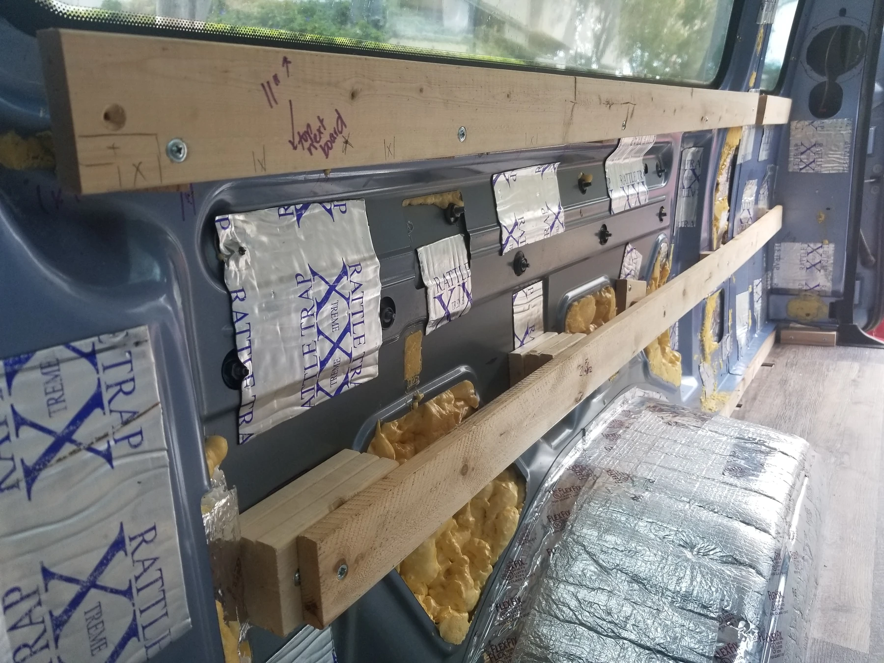
The RattleTrap pieces sit directly on selected metal areas. Their placement is visible on the floor and wheel wells, with additional patches on the walls. In this build record, damping is one stage of the assembly; it is not the material that forms the walking surface.
Notice the exposed steel between the patches. The photographs document the pattern that was installed, but not a measured sound reduction or an optimized coverage percentage. There is no noise test here from which to promise a particular result.
Useful distinction
Sound damping, thermal insulation and the walking deck perform different jobs. Naming each layer makes it easier to compare a proposed floor assembly without treating one material as a substitute for everything else.
Photographed stage
Shape the insulation around the van
The next stage shows foil-faced pieces with cut-outs around the wheel wells and floor edges. R-Tech-branded board appears inside the van, alongside a partly covered floor. The shaped pieces make the geometry of the job much clearer than a finished-floor photograph can.
Work from the actual vehicle when preparing templates. Left and right edges are not automatically identical, and a threshold that looks square in a photograph may not be square in the van. The drawing is an explanation of the layer sequence, not a cutting template.
The archive does not yet establish the exact insulation thickness. It would be misleading to turn the thickness of a drawn layer into a purchase quantity or an R-value.
Photographed stage
Fit the continuous surface
By the evening of April 1, pale panels cover the main floor area, with shaped cuts around both wheel wells and a visible cross-van seam. This is the stage at which the small metal ribs disappear beneath a more continuous surface.
The panel edges and seam are useful details to inspect at full size. The photograph records the fit, but it does not identify the panel material or prove how every concealed point was supported or fastened. Those details remain open in the materials table.
Before committing a similar assembly in another van, check the total build-up at the side door, rear doors and any retained seat bases. Clearances are a vehicle-specific decision; Walter’s finished height has not been measured from this image.
Photographed stage
Lay out the finish before the furniture
The April 6 sequence shows the wood-pattern planks partway across the pale deck. Their staggered ends and the cuts around the wheel well are visible. A knife, mallet and spare pieces sit beside the work, giving a useful view of the installation while the edges are still accessible.
The important planning lesson is the order of access: the floor was photographed before the later bed and kitchen enclosed much of this area. This lets us study joints and perimeter cuts that the finished interior can no longer show.
The installed product, expansion allowances and attachment method need to be matched to the actual flooring record before this becomes a product-specific installation recipe. Use the instructions for your selected floor rather than copying a joint or clearance from an image.
Before moving on to the furniture
- Check door and threshold clearances with the full layer stack in place.
- Keep the manufacturer’s flooring instructions with the project record.
- Photograph the substrate, seams and any service access before covering them.
- Record exact materials, thicknesses and fastening locations; photographs alone may not recover them later.
- Keep vehicle structure, seat mountings and furniture restraints outside a decorative-floor assumption.
Walter’s floor is a useful case study in fitting a complicated shell. Its remaining material questions are recorded openly so the illustrations do not suggest measurements or specifications that the archive has not supplied.
Questions worth answering
Was every metal surface covered with damping mat?
No. The selected floor photograph shows localized RattleTrap patches with steel visible between them. It does not establish a performance target for another vehicle.
Can I use the layer drawing as a cut list?
No. It is an explanatory drawing with exaggerated spacing. It contains no measured panel dimensions, material thicknesses or fastening schedule.
Why is there no claimed floor R-value?
The exact insulation thickness, complete coverage and full assembly have not been established. A material’s laboratory value would not by itself measure the finished van floor.
About these notes
Original build photographs dated March 31–April 6, 2018. Materials are named only where a label is visible; concealed details remain identified as open questions.